Current regulating device

A current regulation and power supply technology, which is applied in the field of dual power supply power supply devices, can solve problems such as current imbalance, input power supply stop power supply, etc., and achieve the effect of improving power transmission capability

Active Publication Date: 2015-05-20
ASUSTEK COMPUTER INC
View PDF5 Cites 0 Cited by
  • Summary
  • Abstract
  • Description
  • Claims
  • Application Information

AI Technical Summary

Problems solved by technology

Obviously, when the current is unbalanced, it may be limited in use, such as the input power supply stops
Because the current imbalance will cause many design bottlenecks, more breakthroughs are needed in technology, which is also the subject to be overcome by the present invention

Method used


Image

  • Current regulating device
  • Current regulating device
  • Current regulating device

Examples


Embodiment Construction

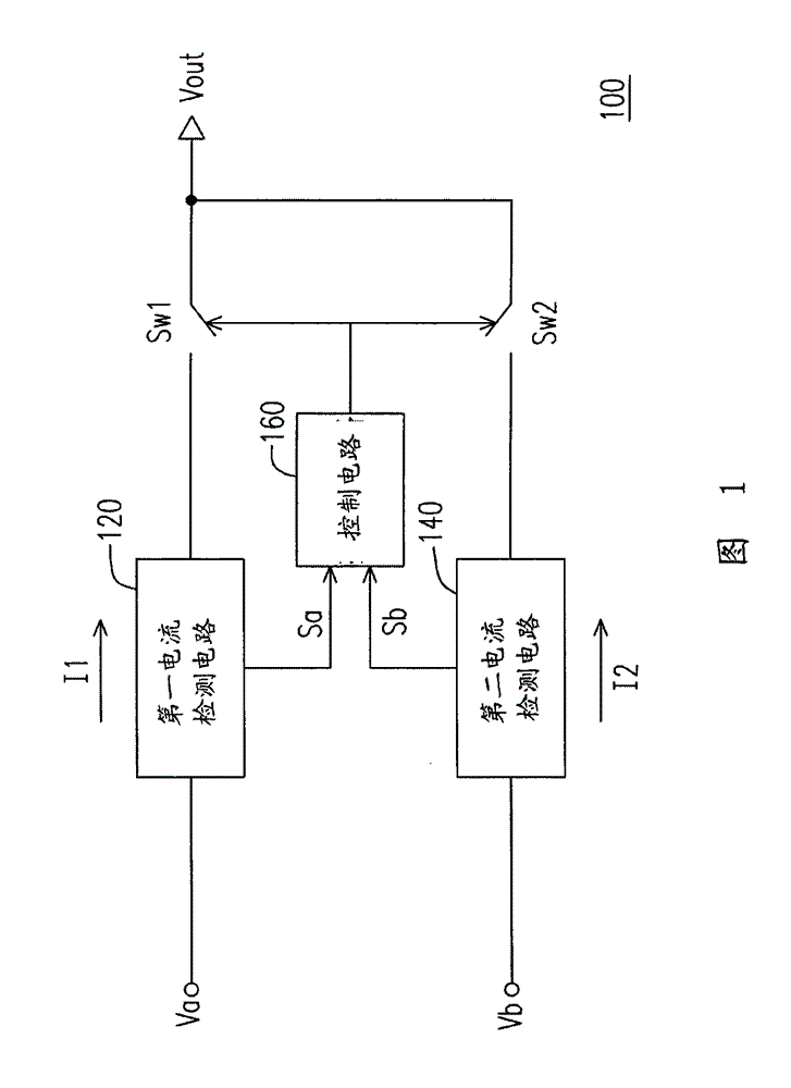
[0014] figure 1 Shown is a circuit block diagram of a current regulating device according to an embodiment of the present invention. The current regulating device 100 may include a switch Sw1 , a switch Sw2 , a first current detection circuit 120 , a second current detection circuit 140 and a control circuit 160 .

[0015] An input terminal of the first current detection circuit 120 is coupled to the first power supply Va. The output terminal of the first current detection circuit 120 is coupled to the first terminal of the switch Sw1. An input terminal of the second current detection circuit 140 is coupled to the second power supply Vb. The output terminal of the second current detection circuit 140 is coupled to the first terminal of the switch Sw2. The control circuit 160 is coupled to the first current detection circuit 120 and the second current detection circuit 140 . The second terminal of the switch Sw1 is coupled to the second terminal of the switch Sw2, and a pow...


PUM


Abstract

The invention discloses a current regulating device, comprising a first switch, a second switch, a first current detection circuit, a second current detection circuit and a control circuit. The first current detection circuit and the second current detection circuit detect the current on respective power source path; and the control circuit controls the on-off state of the first switch and the second switch on the power source path according to a detection signal, thereby the balance of the circuit current can be regulated.

Description

technical field [0001] The invention relates to a power supply device with dual power sources, and in particular to a current regulating device with dual power sources. Background technique [0002] Generally, the power supply mode of the computer peripheral products is to harvest power through the USB interface of the computer or the power over Ethernet (POE) mode. [0003] According to the specification, the maximum power of the USB interface can only provide about 2.5 watts, and the maximum power of the general POE can only provide about 15 watts. If the wattage consumed by the product itself is greater than the maximum wattage that the power supply can provide, then a bottleneck will appear in the design of the product. In order to make the product have a greater input wattage, design engineers usually use two USB ports or two POE ports to be connected in parallel to make the voltage difference between the two power sources as close as possible to avoid power supply. P...

Claims


Application Information

Patent Timeline
Patent Type & Authority Patents(China)
IPC IPC(8): H02J1/10
Inventor 阮飞瑞黄农哲许志琬
Owner ASUSTEK COMPUTER INC
Why Eureka
Try Eureka