
Command back calculation method for numerical control system

A numerical control and calculation method technology, applied in the direction of digital control, electrical program control, etc.

Active Publication Date: 2012-06-27
DELTA ELECTRONICS INC
View PDF4 Cites 0 Cited by
  • Summary
  • Abstract
  • Description
  • Claims
  • Application Information

AI Technical Summary

Problems solved by technology

[0006] Therefore, how to design a command return calculation method for numerical control system, which can achieve the multiple differential continuity of the position polynomial, and overcome the driver and upper control The problem of device asynchrony is the subject that the present invention intends to overcome and solve

Method used


Image

  • Command back calculation method for numerical control system
  • Command back calculation method for numerical control system
  • Command back calculation method for numerical control system

Examples


Embodiment Construction

[0036] Relevant technical content and detailed description of the present invention, cooperate drawing description as follows:

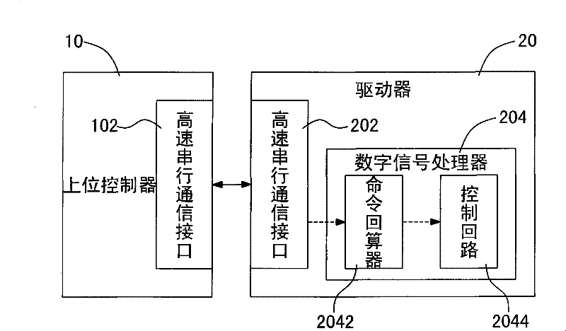
[0037] See figure 1 It is a schematic diagram of communication between a host controller and a driver in the present invention. Taking the electrical system configuration of a CNC machine tool as an example: the host controller 10 generates a periodic position point data by a G-code interpreter (not shown). The host controller 10 is electrically connected to the driver 20 , and the host controller 10 sends a pulse wave position command to the multi-axis AC servo driver 20 . The commands between the host controller 10 and the driver 20 are transmitted through only one transmission line, which makes the wiring simple. The host controller 10 and the driver 20 respectively have a high-speed serial communication interface 102 , 202 . The generation period of a position command of the host controller 10 is T (seconds). Similarly, the driver 20 acquires...


PUM


Abstract

The invention discloses a command back calculation method for a numerical control system. The numerical control system is used in an upper controller for supplying a position command to a servo driver so as to drive a motor. The command back calculation method comprises the following steps: firstly, setting a memory space for storing the position command; secondly, reading a position matrix and a conversion matrix; thirdly, calculating coefficients of a position polynomial and a plurality of position compensation points by multiplying the conversion matrix and the position matrix; and finally, further calculating a velocity polynomial and an acceleration polynomial. Therefore, the back calculation of the position command is performed to reduce the position command into a high-order polynomial of a continuous curve to further achieve the continuity of differentiation of a plurality of times of the position polynomial; and the problem that the driver and the upper controller are asynchronous is solved.

Description

technical field [0001] The invention relates to a command back-calculation method of a numerical control system, in particular to a command back-calculation method that can be restored to a high-order polynomial of a continuous curve. [0002] Background technique [0003] Motion control is the key core technology in precision machining machinery. Its application scope covers industrial machinery with positioning control or speed control to various types of high-precision CNC machine tools. The establishment of a motion control system must integrate various software and hardware technologies. For users, in addition to the basic functional requirements of the system, the cost, system stability, frequency of use, warranty service, and other software and hardware Scalability and compatibility... etc. are also factors for evaluating motion control systems. In addition, in consideration of the actual motion control system, not only the position of each axis must be controlled, b...

Claims


Application Information

Patent Timeline
Patent Type & Authority Patents(China)
IPC IPC(8): G05B19/4103G05B19/416
Inventor 蔡清雄吴家明郑宗信
Owner DELTA ELECTRONICS INC
Learn More