
Method for automatically reading electric quantity data in multi-electric energy meter system

A technology of electricity data and electricity meter, applied in non-electrical signal transmission systems, measurement of electrical variables, signal transmission systems, etc., can solve problems such as limiting copying efficiency, data interference, data congestion, etc., to avoid missed reports and reduce labor. Strength, the effect of improving work efficiency

Inactive Publication Date: 2010-07-07
HEBEI JIAYI ELECTRONICS
View PDF0 Cites 12 Cited by
  • Summary
  • Abstract
  • Description
  • Claims
  • Application Information

AI Technical Summary

Problems solved by technology

This method of meter reading is fast and the data is easy to store, but the existing infrared meter reading method can only read the data of one electric energy meter per operation, which is suitable for the situation where there is only one electric energy meter in the electric meter box, and manual labor is required each time. Enter the identification code of the electric energy meter, which limits the efficiency of copying
When there are 6 or even more meters in the meter box, it is difficult to copy the data, let alone copy the data of multiple meters at the same time, because the infrared meter reading device sends infrared meter reading to the electric energy meter After receiving the signal, each meter will transmit power data to the infrared meter reading device at the same time, and there will be interference between these data, and data congestion will occur, so that the data of each meter cannot be reported successfully.

Method used

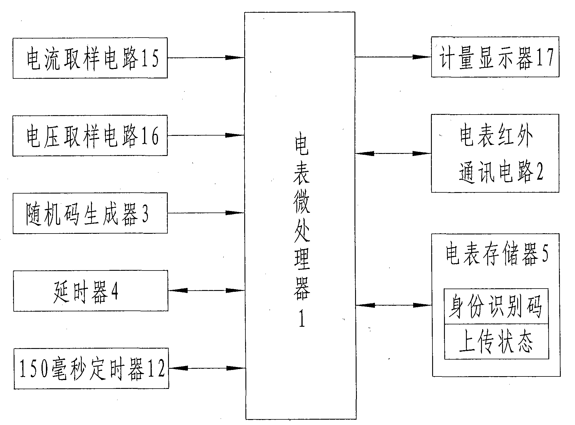
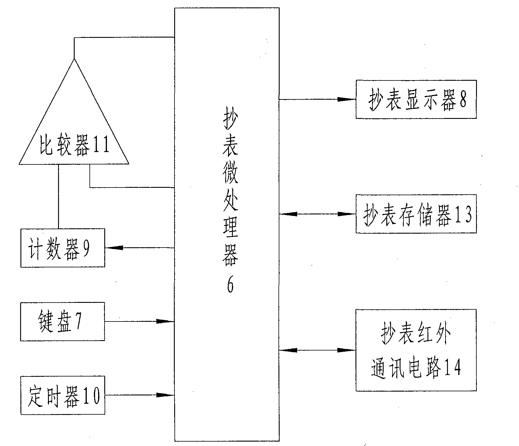
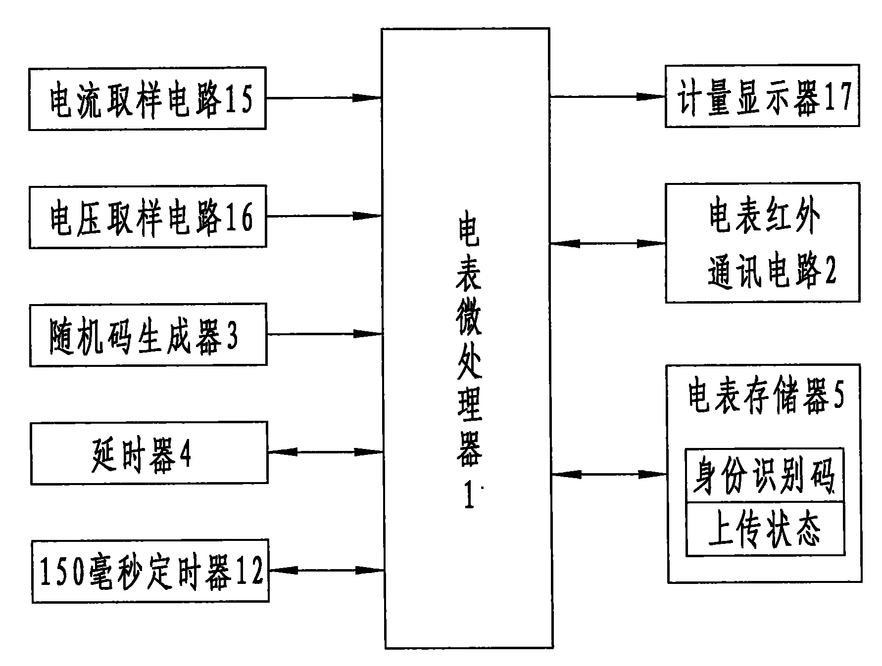

Image

  • Method for automatically reading electric quantity data in multi-electric energy meter system
  • Method for automatically reading electric quantity data in multi-electric energy meter system
  • Method for automatically reading electric quantity data in multi-electric energy meter system

Examples


Embodiment Construction

[0012] For the first meter reading, the data of the electric energy meter in the same meter box that was read back is established in the infrared meter reader database. In the future, the infrared meter reading device can actively search the electric energy meter in the meter box and read the meter by the meter number.

[0013] First reading

[0014] The infrared meter reader sends a broadcast meter reading command (the so-called broadcast meter reading command refers to the meter reading command issued to all meters in the meter box, not for a certain meter, that is, it does not contain a single meter identification code, and all received All meters that broadcast meter reading commands need to upload data. The command contains two parameters: the number of meters in the meter box and the delay factor (the so-called delay factor is a time factor used when the meter calculates the delay time. The time is an integer multiple of the delay factor, and the difference between the delay...


PUM


Abstract

The invention relates to a method for automatically reading electric quantity data in a multi-electric energy meter system, which is used for improving the reading efficiency of the electric quantity data in the multi-electric energy meter system. The invention adopts the technical scheme that each electric energy meter in the system delays the delivery of the identity identification code and theelectric quantity value of the electric energy meter to an infrared meter reader, the length of the delay time is the product of a remainder obtained by using the output value of a random code generator in each electric energy meter for dividing the doubled total of the electric energy meter and a delay factor. The method utilizes the random code to determine the delay time for uploading the dataof each electric energy meter to enable the data uploading time of the electric energy meters to generate difference so that the phenomenon of data congestion generated by simultaneously uploading the data of multiple electric energy meters is avoided, and the automatic reading of the electric quantity data in a multi-electric energy meter system is realized. The method can reduce the labor intensity of meter reading personnel and greatly improve the meter reading efficiency.

Description

Technical field [0001] The invention relates to an infrared meter reading method, which can realize automatic reporting of the electric quantity data of multiple electric (energy) meters in an electric meter box. Background technique [0002] With the increasing development of the power supply industry and the rapid advancement of science and technology, meter reading technology is constantly improving. At present, the more advanced meter reading method is to use infrared meter reader to read and report electricity meter data. The prerequisite for this meter reading method is to install an electronic billing electric energy meter with a microprocessor as the core device and an infrared communication circuit in the line. When reading the meter, first input the identity of the electric meter to the infrared meter reader. Then the infrared meter reader sends an infrared meter reading signal to the electric energy meter. After receiving this signal, the electric energy meter transmi...

Claims


Application Information

Patent Timeline
Patent Type & Authority Applications(China)
IPC IPC(8): G01R22/06G08C23/04
Inventor 游盛翔徐鑫闫广瑞周茜王飞赵毅
Owner HEBEI JIAYI ELECTRONICS
Learn More