
Locking device

A technology of locking devices and locks, which is applied in the direction of fixing devices and mechanical equipment, and can solve the problems of difficult disassembly and low reliability of locking devices

Inactive Publication Date: 2010-07-07
中国航空工业第一集团公司第六三一研究所
View PDF0 Cites 15 Cited by
  • Summary
  • Abstract
  • Description
  • Claims
  • Application Information

AI Technical Summary

Problems solved by technology

[0013] The object of the present invention is to provide a locking device to solve the problems of difficult disassembly and low reliability of existing locking devices

Method used


Image

  • Locking device
  • Locking device
  • Locking device

Examples


Embodiment Construction

[0031] Below in conjunction with accompanying drawing, content of the present utility model is described.

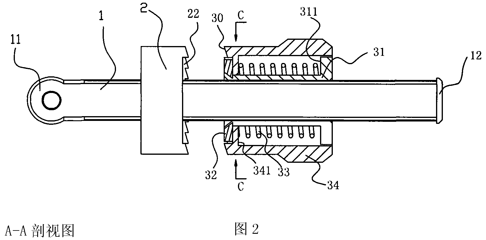
[0032] Such as figure 1 , figure 2 , image 3 , Figure 4 , Figure 5 , Figure 6 As shown: the locking device in the present invention includes a screw rod 1, a lock 2 and a lock wheel 3, the lock 2 and the lock wheel 3 are arranged on the screw 1, the lock 2 is arranged outside the lock wheel 3, and the lock 2 passes through the lock The buckle center hole 21 is sleeved on the screw rod 3, and the direction of the central axis of the screw rod 1 is provided with two first planes 101 and second planes 102 with the same size and shape and symmetrical positions, wherein the width perpendicular to the direction of the central axis of the screw rod 1 , the length of the first plane is the same as that of the screw 1, the width of the first plane and the second is equal to the diameter of the screw, and the shape of the central hole 21 of the lock 2 is corresponding, s...


PUM


Abstract

The invention provides a locking device and mainly solves the difficult detachment and low reliability problems of the traditional locking device. The locking device comprises a threaded rod, a lock catch and a lock wheel, wherein the lock wheel consists of a threaded sleeve, a lock wheel retainer ring, a spring and a lock sleeve; one end of the threaded rod is provided with a fixed hole fixed with equipment, while the other end is provided with the lock wheel retainer ring to prevent the lock wheel from falling off; the lock catch and the lock wheel are both provided with sawteeth; and the lock catch sawteeth are meshed with the lock wheel sawteeth to prevent looseness caused by factors such as shock impact. When the locking device is unlocked for maintenance and replacement, a longitudinal force along the direction of the central axis of the threaded rod can be applied to unlock the sawtooth-meshed parts; and therefore, the locking device is simple in operation and avoids the use of tools.

Description

technical field [0001] The invention relates to a locking device, in particular to a high-strength fast locking and disengaging locking device. Background technique [0002] For equipment that works in a more complex environment, especially equipment that often moves or generates vibrations, such as electronic equipment and precision instruments installed on airplanes and trains, it is necessary to fix the working position to ensure that the equipment is not affected by vibration and inertia. Factors such as location changes affect performance. Because the change of the working position may lead to failure, damage to the circuit, and even the destruction of the entire device or system in severe cases. [0003] While ensuring that the position is fixed, this type of equipment also needs to be easy to disassemble, so that the staff can perform security inspection, maintenance, and replacement of the fixed equipment. [0004] At present, for the fixing of this type of equipme...

Claims


Application Information

Patent Timeline
Patent Type & Authority Applications(China)
IPC IPC(8): F16B1/02
Inventor 杨龙
Owner 中国航空工业第一集团公司第六三一研究所
Learn More