
Network element management system based on virtual technology

A network element management system and technology for virtual network elements, applied in the field of network element management systems, can solve the problems of lack of effective isolation of system resources, offline, poor flexibility, etc., to provide scalability, ensure system security, and avoid resource waste. Effect

Inactive Publication Date: 2010-06-30
GENEW TECH
View PDF0 Cites 25 Cited by
  • Summary
  • Abstract
  • Description
  • Claims
  • Application Information

AI Technical Summary

Benefits of technology

This patented method allows for more efficient resource allocation across various networks without compromising their safety measures. By utilizing this technique, it becomes possible to manage complex systems efficiently while maintaining high levels of privacy and control over each individual component's operations.

Problems solved by technology

The technical problems addressed in this patent text are as follows: 1. Lack of flexibility: Traditional network element management systems are built on specific operating systems or platforms, resulting in differences in resource usage and management strategies. This makes it difficult to define and implement a unified management interface, limiting the system's flexibility to run on different systems or platforms. 2. Limited scalability: Upgrading the network element management software requires stopping the old software and starting the new one, causing downtime and restricting system expansion. This limits the ability to upgrade or expand the system while it is in operation. 3. Poor security: The lack of effective resource isolation in the network element management system can lead to failures in functional modules for all managed objects if one object causes an error. For example, a centralized data management module can fail, affecting the data management functions for all objects. Overall, the patent text highlights the need for improvements in flexibility, scalability, and security in traditional network element management systems.

Method used


Image

  • Network element management system based on virtual technology
  • Network element management system based on virtual technology
  • Network element management system based on virtual technology

Examples


Embodiment Construction

[0020] Various preferred embodiments of the present invention will be described in more detail below in conjunction with the accompanying drawings.

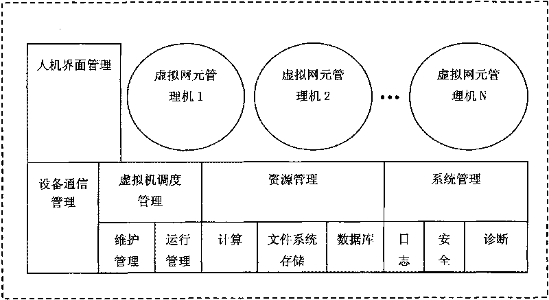
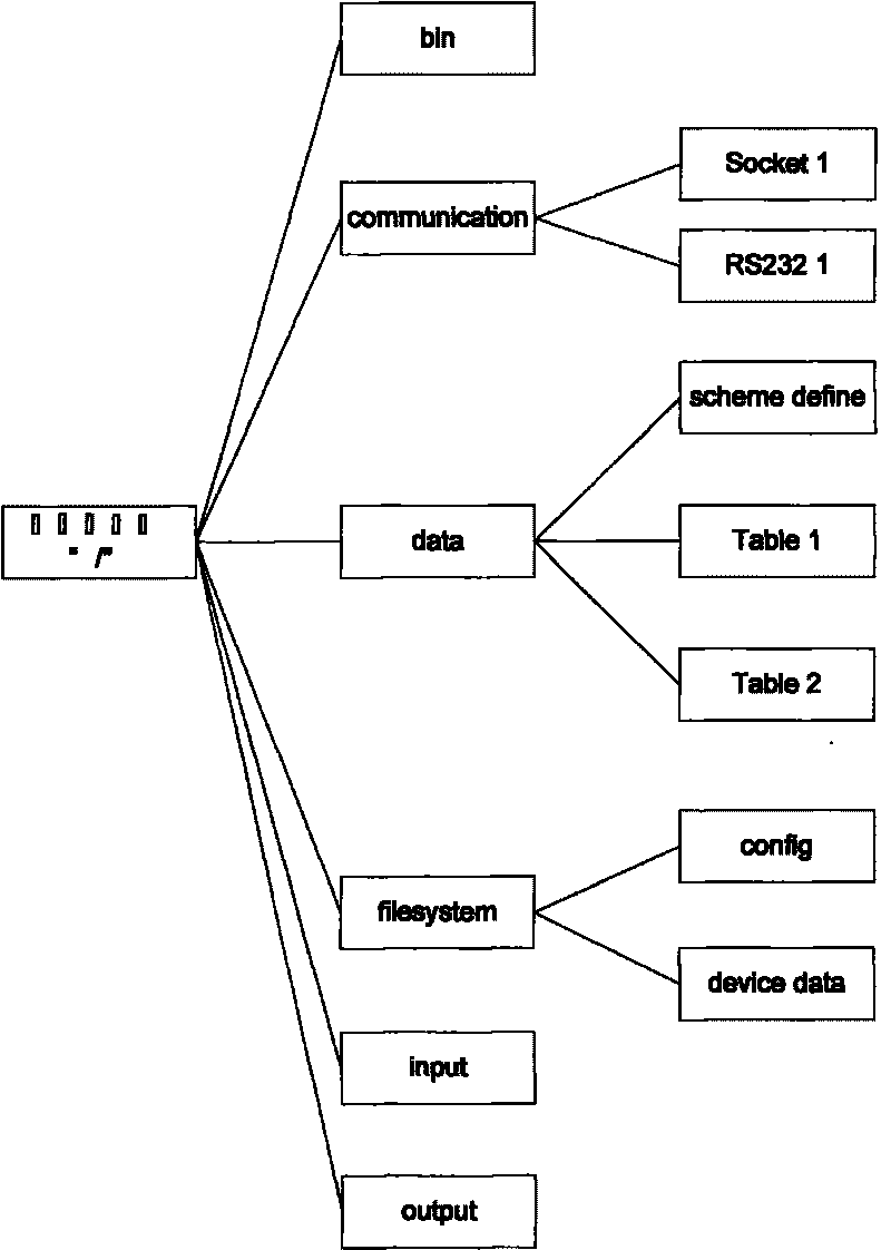
[0021] In the present invention, the production process of the network element management virtual machine: complete the development of the management program for specific equipment in the development environment of the network element system, and virtualize the associated resources during the binary code process of the product network element management program processing; set a virtual top-level directory, and organize all files related to the network element management virtual machine in this directory, so as to figure 2 For example, through a tree-like organizational structure, the running programs, file systems, and databases involved in the network element management virtual machine are organized into a virtual top-level directory, and the content is packaged into a virtual machine data file.

[0022] In the present inventi...


PUM


Abstract

The invention aims to provide an implementing method for network element management system. The system comprises virtualization of input equipment, output equipment, storage equipment and communication resource, each target management object in the network element management system is processed by an independent virtual machine and the virtualized resource is subject to exclusive access. The whole system is composed of human-computer interface management, equipment communication management, virtual machine scheduling management, resource management, system management and one or a plurality of virtual network element supervisors. The processing method for the system comprises: packing network element management executing code for managing specific equipment and data resource to manufacture the virtual network element supervisors; loading the network element supervisors into the network element management system to configure input and output equipments, communication interface, file system and database resource; starting the network element supervisors to operate, communicating with the equipments to be managed by the virtual network element supervisors, and managing the equipments by network element management interface. In the invention, implementation based on virtualization technology is adopted to concentrate network element management function for specific equipments in a single virtual machine, and virtual machines are completely isolated, thus ensuring safety of system, greatly enhancing expandability of system and fully utilizing processing capacity of computer.

Description


Claims


Application Information

Patent Timeline
Owner GENEW TECH
Learn More