


Quick Research
Generate reliable direction feasibility study reports for your R&D in just a few steps.

Technical Q&A
Discover and master advanced knowledge NOW. Basics, ideas, possibilities, all at once.

Find Solutions
As an expert in R&D theories, this can generate solutions to your technical problems instantly.

Evaluate Feasibility
Analyze your overall solution with one click, know your potential R&D risks in advance.

Monitor Landscape
Get weekly tech updates, stay abreast of the latest tech innovations and key insights.
Chair type massage machine
A massager and chair-type technology, applied in the field of chair-type massagers, can solve the problems of inability to realize, difficult to realize automation, etc.
- Summary
- Abstract
- Description
- Claims
- Application Information
AI Technical Summary
Problems solved by technology
Method used
Image

Examples
Embodiment approach 1
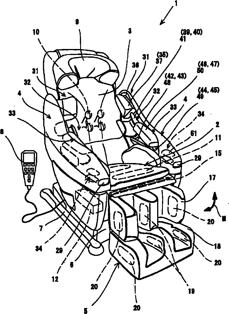
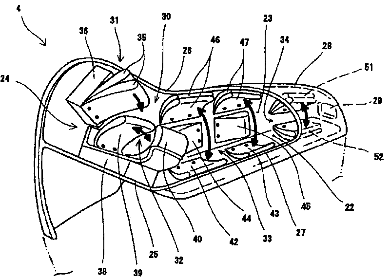
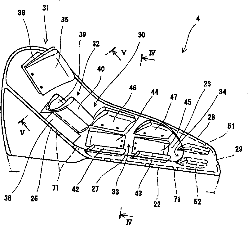
[0193] Hereinafter, one embodiment of the present invention will be described based on the drawings. figure 1It is a perspective view of a chair type massager according to an embodiment of the present invention, figure 2 means seen from the upper part of the inside figure 1 A perspective view of the state of the armrest of the chair massager shown, image 3 seen from the inside figure 2 A side view of the upper half of the armrest portion shown, Figure 4 yes image 3 Illustrated in the IV-IV sectional view, Figure 5 yes image 3 shown in the V-V cross-section diagram, Figure 6 yes means Figure 4 A cross-sectional view of a modification of the cross-section shown, Figure 7 means seen from the outside figure 2 The side view of the armrest part shown (wherein, the treatment part is briefly shown), and the concept of the direction in the specification and claims documents is consistent with the concept of the state of the treated person sitting on the seat facin...
Embodiment approach 2
[0217] Next, the structure of Embodiment 2 about the chair type massager of this invention is demonstrated. The chair type massager of the present embodiment possesses and utilizes Figure 1 to Figure 7 The chair massager 1 according to Embodiment 1 described above has the same configuration, and the configuration related to the massage operation of the chair massager 1 will be mainly described below.
[0218] Figure 8 is used for figure 2 shown in the block diagram illustrating the functionality of the therapy section, Figure 9 is expressed by Figure 8 A timing diagram of an example of a massage performed by the treatment unit shown, Figure 10 is expressed by Figure 8 A time chart of another example of the massage performed by the treatment unit shown. In addition, in these figures, only the control related to the airbags 35, 39, 40, 42-47, 51, 52 provided on the armrest 4 as the treatment part will be described, and the other airbags related to the chair massager ...
Embodiment approach 3
[0229] Next, a massage device according to Embodiment 3 of the present invention will be specifically described with reference to the drawings. Figure 11 It is a perspective view which shows the whole structure of the chair type massager which concerns on embodiment of this invention. Such as Figure 11 As shown, the chair massager 101 is mainly composed of a seat 102 on which the person to be treated sits, a backrest 103 which supports the upper body of the person to be treated from behind, an armrest 104 which supports the arms of the person to be treated, and a foot which supports the person to be treated. The pedal 105 constitutes.
[0230] 〔Overall composition〕
[0231] The seat portion 102 is provided on a seat frame 102b ( Figure 11 , a part of which is shown in the figure) is configured by disposing a substantially flat cushion pad on the upper part. The cushion pad is formed by covering an inner material such as urethane foam, sponge, or expanded styrene with an...
PUM
 Abstract
Description
Claims
Application Information
 - R&D Engineer
- R&D Manager
- IP Professional
- Industry Leading Data Capabilities
- Powerful AI technology
- Patent DNA Extraction
Browse by: Latest US Patents, China's latest patents, Technical Efficacy Thesaurus, Application Domain, Technology Topic, Popular Technical Reports.
© 2024 PatSnap. All rights reserved.Legal|Privacy policy|Modern Slavery Act Transparency Statement|Sitemap|About US| Contact US: help@patsnap.com