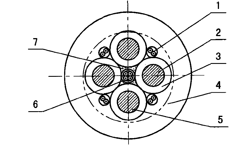
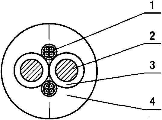
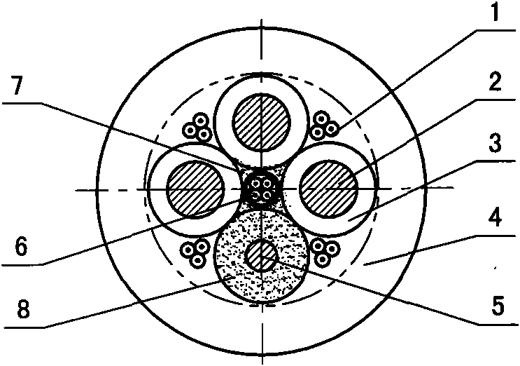
Combined using method for optical cable and mine cable and mine cable as fiber-optical communication

A technology of optical fiber communication and optical fiber cable, which is applied in the fields of optical fiber communication and underground power supply in coal mines. It can solve the problems of less laying, unsolvable information islands of underground electrical equipment, and small coverage, so as to save costs, save cable connections and explosion-proof equipment, Solve the effect of multiple information sharing channels

Active Publication Date: 2010-06-23
赵振海
View PDF0 Cites 19 Cited by
  • Summary
  • Abstract
  • Description
  • Claims
  • Application Information

AI Technical Summary

Problems solved by technology

[0003] In order to overcome the shortcomings of the existing underground optical cables in coal mines, such as less laying, small coverage, and inability to solve the problem of information islands caused by explosion-proof underground electrical equipment, the present invention provides a The combined use of optical cable and mine cable can solve the optical fiber communication between underground electrical equipment, fully realize the optical fiber communication in coal mine underground, and greatly improve the coverage of optical fiber communication

Method used


Image

  • Combined using method for optical cable and mine cable and mine cable as fiber-optical communication
  • Combined using method for optical cable and mine cable and mine cable as fiber-optical communication
  • Combined using method for optical cable and mine cable and mine cable as fiber-optical communication

Examples


Embodiment

[0129] Example: connection method in mine explosion-proof low-voltage vacuum feed switch

[0130] 1. Application: Mining explosion-proof vacuum feed switch, referred to as low-voltage feed switch, is suitable for use as a switch in a mobile substation or as a general feed, intermediate feed, sub-feed or single use in a power distribution system. When multiple units form a system, it can realize three-level leakage protection and overload, short circuit, leakage, undervoltage and overvoltage protection.

[0131] 2. Structure: Take the structure of KBZ-630 / 1140 flameproof low-voltage feeder switch as an example to illustrate.

[0132] Figures 23 to 25 Shows the structure of a KBZ-630 / 1140 low-voltage switch. The flameproof shell is square and divided into upper and lower cavities, namely the main cavity 31 and the wiring cavity 33 . The flameproof enclosure is mounted on the skid-shaped chassis 30. The explosion-proof wiring cavity 33 is above the main cavity 31, and all th...


PUM


Abstract

The invention provides a combined using method for an optical cable and a mine cable and the mine cable used as fiber optical communication, which is to arrange the optical fiber in the mine cable to ensure that the optical fiber and the cable are combined to a whole to form the mine cable used as fiber optical communication. In a connecting line cavity of explosion-proof type electrical equipment of high voltage feed switch, a low voltage feed switch, an electromagnetic initiator and the like, the end of the optical cable is manufactured into a pigtail and is connected with an optical interface of an optical transmitter and receiver through an optical fiber connector and a jumper; the optical transmitter and the receiver is connected with an intelligent integrated protective device in a main cavity through a communication interface; the jumper and the optical transmitter and receiver are connected through an optical cable explosion-proof cavity connection device, or are connected through wiring terminals on a separator of two cavities; and non-disconnected connection of non explosion proof equipment and the explosion proof high voltage equipment can adopt an optical fiber connector. The optical cable and the cable are combined into a whole without impacting fracture and insulation of the cable, so that the underground optical cable applying range is the same as that of cables to solve the problem of optical fiber communication between electric equipment; and the method saves cost because the optical cable is not required to be applied independently, so that the underground power supply and fiber-optical communication can be organically combined.

Description

technical field [0001] The present invention relates to the field of coal mine power supply and optical fiber communication, in particular to a combined use method of optical cable and mine cable which is suitable for coal mine underground environment with explosive dangerous gas (methane) and coal dust and organically combines optical cable communication with mine power supply And it doubles as a mining cable for optical fiber communication. Background technique [0002] With the advancement of technology, optical fiber communication has been rapidly developed and popularized. However, the application in underground coal mines is relatively limited. The reason is that due to the particularity of underground coal mines—an environment with explosive dangerous gas (methane) and coal dust, the laying and connection of optical cables, especially the conversion of optical signals and electrical signals are restricted by explosion protection, making the laying of underground opti...

Claims


Application Information

Patent Timeline
IPC IPC(8): G02B6/44H01B11/22
Inventor 赵振海赵嘉琦王红
Owner 赵振海
Why Eureka
Try Eureka