
Patsnap Eureka
For R&D, Patsnap Eureka makes reading and utilizing patents & technical documents easy.
Patsnap Eureka AIR
Designed for self-driven R&D workflows. Generate viable solutions, solve complex R&D challenges, empower your innovation with AI.

Patsnap Eureka Materials
Designed for material experts only. Revolutionize your material R&D, from search, analyze, to developing new materials.

TechResearch
Generate reliable direction feasibility study reports for your R&D in just a few steps.

TechSeek
Discover and master advanced knowledge NOW. Basics, ideas, possibilities, all at once.

TechMind
As an expert in R&D Theories, TechMind can generates customized viable solutions instantly.

TechRisk
Analyze your overall solution with one click, know your potential R&D risks in advance.

TechMonitor
Get weekly tech updates, stay abreast of the latest tech innovations and key insights.
Cast-in-situ high-strength light floor system for buildings
A high-strength, cast-in-place technology, applied in the on-site preparation of floor slabs, building components, formwork/template/work frame, etc., can solve the problems of unreasonable structure, uneven bottom surface, poor economy, etc. Improve the overall anti-crack and maintain the effect of stability
- Summary
- Abstract
- Description
- Claims
- Application Information
AI Technical Summary
Problems solved by technology
Method used
Image

Examples
Embodiment 1
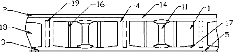
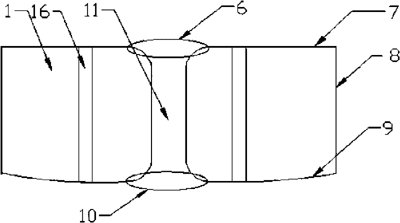
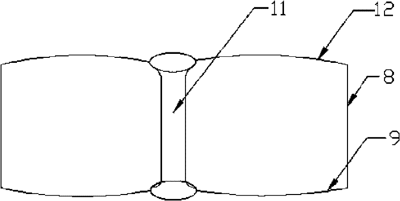
[0025] With reference to the accompanying drawings, the bottom plate 9 and the frame body 8 of the hollow body 1 are made in the mold at one time, generally using special cement to pour, and a class of linings such as glass fiber filaments, glass fiber cloth, and steel wire mesh are added in the middle of the special cement. To enhance the firmness and compression resistance of the hollow body 1, two or three or four arcs 15 protruding outward are made on the bottom surface of the mold. The barbed wire 3 laid between the edge plates 17 is in point contact, and the multi-arc shape can make the bottom 9 of the hollow body 1 form a channel infiltrated into the concrete mortar. This scheme can realize the smooth bottom surface of the lower flange plate 17. The arcs of the bottom surface of the hollow body 1 are symmetrically arranged, and the size of the arc 15 can be adjusted with the size of the hollow body 1. It should be as large as possible under the premise of ensuring the pa...
Embodiment 2
[0028] Using the same pouring method as above, in some buildings where the load-bearing requirements of the floor are not large, foam plastic blocks can be used to make the hollow body 1. The body style is the same, the middle is solid foam plastic, and the through channel 11 in the middle is realized by reserving or digging through the foam plastic block. When installing this hollow body, the bottom of the hollow body of the foam plastic block cannot be directly placed on the building template 5 Above, it should be more than 3 millimeters away from the building formwork 5, and the height of the arc-shaped protrusion 15 of the bottom plate 9 is less than the thickness of the lower flange plate of the floor and less than 18 millimeters.
PUM
 Abstract
Description
Claims
Application Information
 - R&D Engineer
- R&D Manager
- IP Professional
- Industry Leading Data Capabilities
- Powerful AI technology
- Patent DNA Extraction
Browse by: Latest US Patents, China's latest patents, Technical Efficacy Thesaurus, Application Domain, Technology Topic, Popular Technical Reports.
© 2024 PatSnap. All rights reserved.Legal|Privacy policy|Modern Slavery Act Transparency Statement|Sitemap|About US| Contact US: help@patsnap.com