Multi-band antenna

A technology of multi-band antennas and microstrip lines, applied to antennas, resonant antennas, and devices that enable antennas to work in different bands at the same time, can solve the problems of transmitting and receiving signals (communication quality deterioration, etc.) and achieve good communication quality, meet the multi-frequency communication function, and increase the effect of operating bandwidth

Active Publication Date: 2010-06-16
PEGATRON
View PDF0 Cites 12 Cited by
  • Summary
  • Abstract
  • Description
  • Claims
  • Application Information

AI Technical Summary

Problems solved by technology

As the size of the antenna shrinks, the efficiency of transmitting and receiving signals (communication quality) of the antenna will also deteriorate

Method used


Image

  • Multi-band antenna
  • Multi-band antenna
  • Multi-band antenna

Examples


Embodiment Construction

[0020] The multi-band antenna of the present invention can be mainly applied in the field of mobile phone communication, so as to satisfy the multi-frequency communication function of the mobile phone. For example, the communication frequency bands of mobile phones are 880~960MHz regulated by Global System for Mobile Communications 900 (GSM 900), 1710~1880MHz regulated by Distributed Control System (Distributed Control System, DCS), personal communication service (Personal Communications Service, PCS) 1850~1990MHz and Wide band Code Division Multiple Access (WCDMA) 1920~2170MHz.

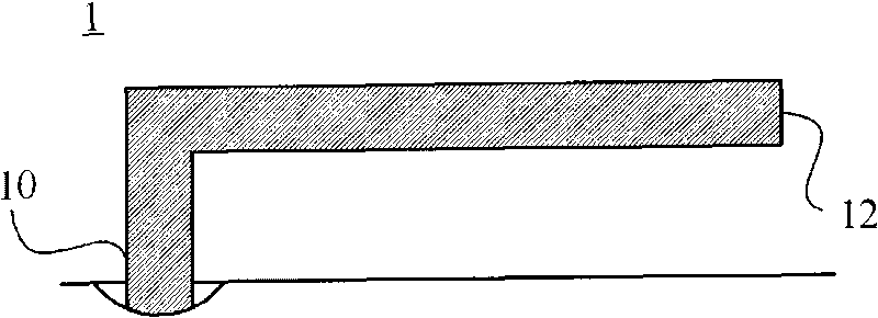
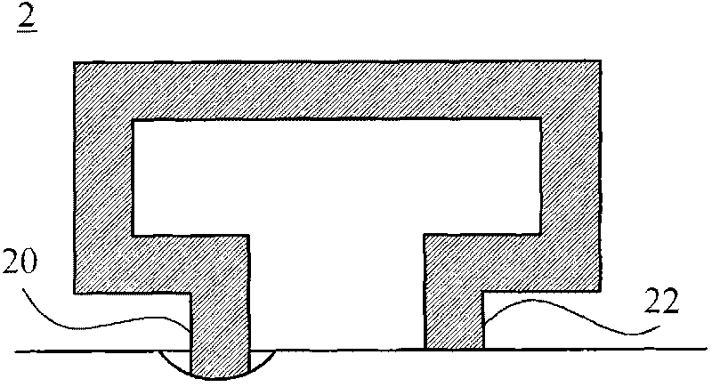
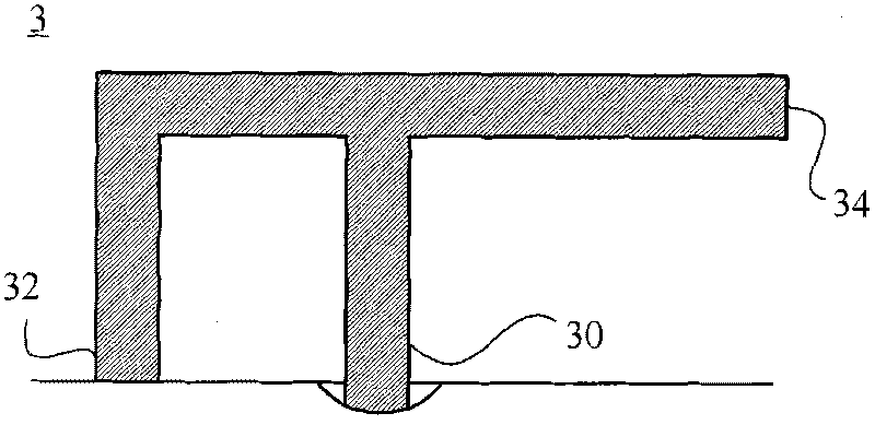
[0021] The multi-band antenna of the present invention can excite electromagnetic waves of different frequencies in a limited volume mainly through special microstrip line configuration and electromagnetic radiation coupling, and maintain good communication quality. For how the multi-band antenna of the present invention achieves the above results, please refer to the description of the following emb...


PUM


Abstract

The invention discloses a multi-band antenna which comprises a loop micro-strip line and a parasitic micro-strip line, wherein the loop micro-strip line comprises a signal feeding end and a first grounding end; a route from the signal feeding end to the first grounding end is half of a wavelength; the parasitic micro-strip line comprises a second grounding end and a first open end; a route from the first open end to the second grounding end is a quarter of the wavelength; a signal is input from the signal feeding end in order to arouse a first resonance modal frequency via the loop micro-strip line; the parasitic micro-strip line is encircled by the loop micro-strip line; an electromagnetic radiation of the first resonance modal frequency is coupled with the parasitic micro-strip line in order to arouse a second resonance modal frequency via the parasitic micro-strip line; and the second resonance modal frequency is different from the first resonance modal frequency. The multi-band antenna of the invention utilizes the loop micro-strip line to encircle the parasitic micro-strip line, realizes the function of multi-frequency communication and keeps high communication quality in a limited accommodating space.

Description

technical field [0001] The invention relates to a multiband antenna (multiband antenna), in particular to a multiband antenna capable of multi-frequency communication within a limited volume and maintaining good communication quality. Background technique [0002] see Figure 1 to Figure 3 , traditional antennas include a monopole antenna (Monopole antenna) 1 , a loop antenna (Loop antenna) 2 and a planar inverted-F antenna (Planar Inverted-F Antenna, PIFA) 3 . The resonant modal frequency of the electromagnetic wave excited by the monopole antenna 1 is determined by the path length between the signal feed-in end 10 and the open-circuit end 12; the resonant modal frequency of the electromagnetic wave excited by the loop antenna 2 is from the signal feed-in end 20 to the ground Determined by the length of the path between the ends 22; the planar inverted F-type antenna 3 is similar to the combination of the loop antenna 2 and the monopole antenna 1, and can excite electromagn...

Claims


Application Information

Patent Timeline
Patent Type & Authority Applications(China)
IPC IPC(8): H01Q1/38H01Q5/00H01Q9/30H01Q13/08H01Q5/10H01Q5/28H01Q5/378
Inventor 黄金鼎
Owner PEGATRON
Why Eureka
Try Eureka