


Quick Research
Generate reliable direction feasibility study reports for your R&D in just a few steps.

Technical Q&A
Discover and master advanced knowledge NOW. Basics, ideas, possibilities, all at once.

Find Solutions
As an expert in R&D theories, this can generate solutions to your technical problems instantly.

Evaluate Feasibility
Analyze your overall solution with one click, know your potential R&D risks in advance.

Monitor Landscape
Get weekly tech updates, stay abreast of the latest tech innovations and key insights.
Power shunt type combined planetary reducer
A planetary reducer and split-flow technology, applied in mechanical equipment, differential transmission, belt/chain/gear, etc., can solve the problems of long cycle, high cost, large area for process layout, etc. Manufacturing cycle, compact structure
- Summary
- Abstract
- Description
- Claims
- Application Information
AI Technical Summary
Problems solved by technology
Method used
Image

Examples
Embodiment 1
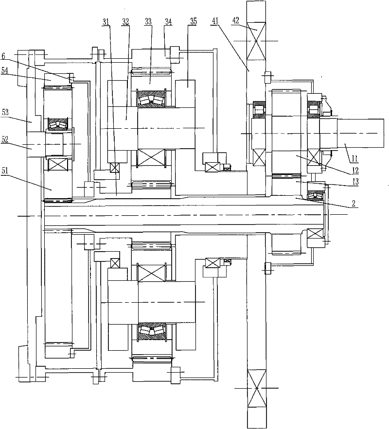
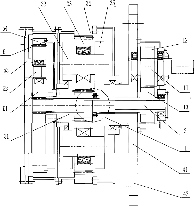
[0025] Such as figure 1 As shown, the power-split combined planetary reducer described in the present invention includes an input gear pair, a differential planetary gear pair, a closed planetary gear pair placed between the input gear pair and the differential planetary gear pair, and a flexible shaft 2 And the support rod 41, the flexible shaft 2 is supported on the support rod 41 through the first bearing, the two ends of the support rod 41 are supported on the torque frame mechanism through joint bearings, and the torque frame mechanism is fixed on the civil foundation, and the flexible shaft 2 is a load equalizing mechanism, the input gear pair includes an input shaft 11, a driving gear 12 and a driven gear 13, the input shaft 11 is supported on the support rod 41 through a second bearing, the driving gear 12 is connected with the input shaft 11, and The driven gear 13 is connected with the flexible shaft 2, and the driving gear 12 is meshed with the driven gear 13; the c...
Embodiment 2
[0029] The technical solution described in embodiment 2 is basically the same as that of embodiment 1, except that in embodiment 2, a shaft for connecting the differential ring gear 54 and the closed sun gear 31 is provided between the stationary planetary carrier 35 and the closed sun gear 31 The wear-resistant and shock-absorbing thrust device to limit, the wear-resistant and shock-absorbing thrust device includes a steel substrate 72, an elastic plastic thrust layer 71 and a shock-absorbing spring layer 73, and the elastic plastic thrust layer 71 is arranged on the steel substrate 72 and the shock-absorbing spring layer 73. The sun gear 31 is closed, and the damping spring layer 73 is arranged between the steel base 72 and the stationary planet carrier 35 .
[0030] The elastic plastic thrust layer 71 is made of polytetrafluoroethylene material, and the elastic plastic thrust layer 71 and the steel substrate 72 are directly bonded together through an adhesive; or the elastic...
PUM
 Abstract
Description
Claims
Application Information
 - R&D Engineer
- R&D Manager
- IP Professional
- Industry Leading Data Capabilities
- Powerful AI technology
- Patent DNA Extraction
Browse by: Latest US Patents, China's latest patents, Technical Efficacy Thesaurus, Application Domain, Technology Topic, Popular Technical Reports.
© 2024 PatSnap. All rights reserved.Legal|Privacy policy|Modern Slavery Act Transparency Statement|Sitemap|About US| Contact US: help@patsnap.com