Outer rotor rotary type magnetic fluid travelling wave pump

A magnetic fluid, rotary technology, used in electrical components, electromechanical devices, etc.

Inactive Publication Date: 2012-06-06
HARBIN INST OF TECH
View PDF5 Cites 0 Cited by
  • Summary
  • Abstract
  • Description
  • Claims
  • Application Information

AI Technical Summary

Problems solved by technology

[0003] In order to solve the problem that there is no external rotor rotating type magnetic fluid traveling wave pump for analyzing the movement law of the magnetic fluid caused by the traveling wave magnetic field, the present invention further provides an outer rotor rotating type magnetic fluid traveling wave pump

Method used


Image

  • Outer rotor rotary type magnetic fluid travelling wave pump
  • Outer rotor rotary type magnetic fluid travelling wave pump
  • Outer rotor rotary type magnetic fluid travelling wave pump

Examples


specific Embodiment approach 1

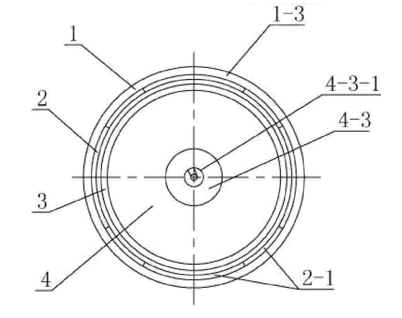
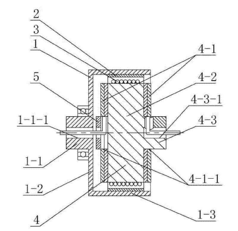
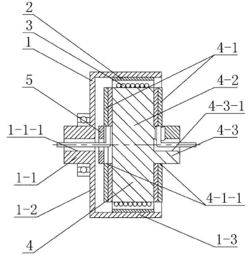
[0007] Specific implementation mode one: as Figure 1~2 As shown, the outer rotor rotating type magnetic fluid traveling wave pump in this embodiment includes a rotor 1, a permanent magnet 2, a coil tube 3 and a stator 4, and the rotor 1 is composed of a first non-magnetically conductive shaft 1-1, a cover plate 1-2 and a cylinder 1-3, one end of the first non-magnetic shaft 1-1 is fixed at the center of the cover 1-2, and the two ends of the cover 1-2 are respectively connected to the cylinder 1- The end of 3 is fixed as a whole, the material of cover plate 1-2 and cylinder 1-3 is magnetic steel, and the cylinder 1-3 is fixedly sleeved on the permanent magnet 2, and the permanent magnet 2 is composed of an even number The permanent magnet monomers 2-1 are magnetized in the axial direction, and the magnetization directions of two adjacent permanent magnet monomers 2-1 are opposite. The stator 4 consists of a magnetically conductive core 4-2, a second nonmagnetically conductive...

specific Embodiment approach 2

[0008] Specific implementation mode two: as figure 2 As shown, the traveling wave pump in this embodiment also includes a fastener 5, which is fixedly sleeved on the coil 3 between the cover plate 1-2 and the magnetic isolation plate 4-1, and the fastener 5 The firmware 5 is made of non-magnetic material. Such setting can play the role of fastening the coil pipe 3 . Other components and connections are the same as those in the first embodiment.

[0009] working principle:

[0010] According to fluid dynamics and electromagnetic field theory, an outer rotor rotating type magnetic fluid traveling wave pump is designed. After the coil 3 is filled with magnetic fluid, the first non-magnetic-conductive shaft 1-1 and the second non-magnetic-conductive shaft 4-3 of the outer rotor rotating type magnetic fluid traveling wave pump are installed on the non-magnetic support. The motor drives the rotor 1 to rotate. Since the rotor 1 is fixedly sleeved on the permanent magnet 2, the...


PUM


Abstract

The invention discloses an outer rotor rotary type magnetic fluid travelling wave pump, relating to a magnetic fluid travelling wave pump. The invention solves the problem that there is no outer rotor rotary type magnetic fluid travelling wave pump used for analyzing characteristics of motion of magnetic fluid affected by travelling wave magnetic field at present. The rotor is fixed on a permanent magnet in a sleeved manner, the permanent magnet consists of permanent magnetic single bodies with an even number magnetizing along an axial direction, and the magnetizing directions of two adjacentpermanent magnetic single bodies are opposite; a stator consists of two magnetic separation sheets, a magnetic conductive iron core and a second non-magnetic conductive shaft, the magnetic iron core is fixedly arranged on the second non-magnetic conductive shaft, a coil pipe is sleeved on the magnetic conductive iron core, two side end faces of the magnetic conductive iron core are both provided with the magnetic separation sheets, the stator and the coil pipe are both arranged in a cylinder, and the magnetic fluid is filled in the coil pipe. The invention provides the outer rotor rotary typemagnetic fluid travelling wave pump by using the magnetic fluid kinetic principles. By adopting the invention, the carrying characteristics of the magnetic fluid can be validated, thereby a new fieldof the magnetic fluid application is developed.

Description

technical field [0001] The invention relates to an outer rotor traveling wave pump, in particular to an outer rotor rotating type magnetic fluid traveling wave pump for analyzing the movement rule of the traveling wave magnetic field on the magnetic fluid. Background technique [0002] At present, the research on magnetohydrostatics is relatively in-depth, and gratifying achievements have been made in the application, but there is no research on the research on magnetohydrodynamics, especially on the effect of traveling wave magnetic field. The prior art does not provide an outer rotor rotating magnetic fluid traveling wave pump for analyzing the movement rule of the traveling wave magnetic field on the magnetic fluid. Contents of the invention [0003] In order to solve the problem that there is no outer rotor rotating type magnetic fluid traveling wave pump for analyzing the movement rule of the magnetic fluid by the traveling wave magnetic field, the present invention f...

Claims


Application Information

Patent Timeline
Patent Type & Authority Patents(China)
IPC IPC(8): H02K44/06
Inventor 赵猛邹继斌胡建辉徐永向尚静赵博
Owner HARBIN INST OF TECH
Why Eureka
Try Eureka