
Laser self-adoptive trace adjustment system

An adjustment system and self-adaptive technology, applied in transmission systems, electromagnetic wave transmission systems, free space transmission, etc., can solve problems such as large errors, misalignment of optical signals to receivers, and unrealizable communication, and achieve low additional noise and laser low loss effect

Inactive Publication Date: 2013-01-30
SHANDONG UNIV
View PDF0 Cites 0 Cited by
  • Summary
  • Abstract
  • Description
  • Claims
  • Application Information

AI Technical Summary

Problems solved by technology

[0031] In strong winds or due to the shaking of the building due to earthquakes, the optical signal sent by the transmitter is not aligned with the receiver, resulting in large errors, and even communication cannot be realized
The current research direction is to improve laser aiming, how to use non-mechanical devices to achieve precise alignment and fast aiming; in terms of receivers, scattered light also carries information, the more scattered light is received, the greater the received signal energy, But at the same time, the received noise is also greater, so it is the research goal to increase the total power of the receiver received signal without reducing the signal-to-noise ratio.

Method used


Image

  • Laser self-adoptive trace adjustment system
  • Laser self-adoptive trace adjustment system
  • Laser self-adoptive trace adjustment system

Examples


Embodiment Construction

[0068] The present invention will be further described below in conjunction with the accompanying drawings and embodiments.

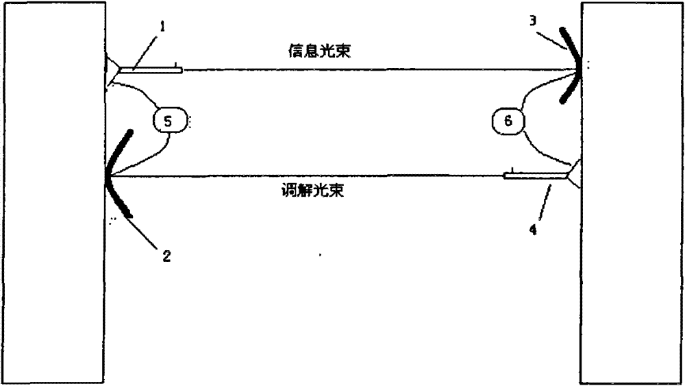
[0069] figure 1 Among them, it includes an information gun 1, which cooperates with the information target 3; it also includes an adjustment gun 4, which cooperates with the adjustment target 2; a controller I5 is arranged between the information gun 1 and the adjustment target 2, and the adjustment A controller II6 is arranged between the gun 4 and the information target 3 .

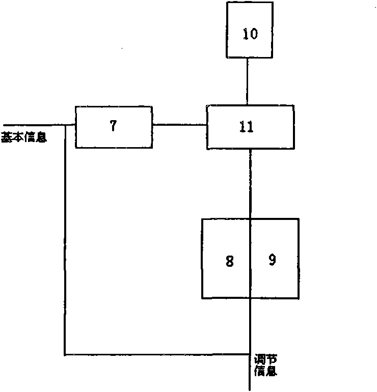
[0070] figure 2 Among them, the information gun 1 includes a modulator I7, a mechanical transmission device 8, a power control device I9, a temperature control device I10 and a laser emitter I11, and the modulator I7 modulates the basic information to be emitted and the adjustment information generated by the controller I5 to the laser emission On the device I11, the required information laser beam is generated and emitted; the mechanical transmission device 8 adjusts the angl...


PUM


Abstract

The invention relates to a laser self-adoptive trace adjustment system with simple structure and convenient use. The laser self-adoptive trace adjustment system comprises an information gun which is matched with an information target, and an adjustment gun which is matched with an adjustment target. A controller I is arranged between the adjustment gun and the adjustment target, and a controller II is arranged between the adjustment gun and the information target.

Description

technical field [0001] The invention belongs to the technical field of wireless optical access, in particular to a laser adaptive tracking adjustment system for aiming and tracking laser signal emission and reception. Background technique [0002] With the advent of the information society, communication technology has also been developing with each passing day. In the past few years, people have higher and higher requirements on the transmission rate, and the number of users who use high-speed data transmission is increasing every year. Because optical fiber communication can transmit high-speed data, it has become the backbone network of the wide area communication network. Today, more than 80% of the information in the wide area communication network is transmitted through optical fibers. But from the optical fiber backbone network to the "last mile" between users, if laying optical cables, it will not only cost a lot but also time-consuming; many wireless communication ...

Claims


Application Information

Patent Timeline
Patent Type & Authority Patents(China)
IPC IPC(8): H04B10/00H04B10/11
Inventor 王洪君杨斌栗华张纯波王纯纯
Owner SHANDONG UNIV
Learn More