
Method and device for measuring multispectral dynamic modulation transfer function

A technology of modulation transfer function and transfer function, which is applied in the direction of testing optical performance, etc., can solve problems such as unrealistic, measured dynamic modulation transfer function, and incomplete dynamic modulation transfer function, and achieve the effect of improving applicability

Inactive Publication Date: 2010-06-02
BEIJING INSTITUTE OF TECHNOLOGYGY
View PDF0 Cites 18 Cited by
  • Summary
  • Abstract
  • Description
  • Claims
  • Application Information

AI Technical Summary

Problems solved by technology

However, its shortcoming is that the paper only conducts theoretical analysis and numerical simulation of the dynamic modulation transfer function under different vibration forms, and does not actually measure
However, the simulation system used by this method is very complicated, and the same system cannot be used for simulation of vibrations in different frequency ranges, and the dynamic modulation transfer function cannot be measured simply and quickly, so it is not suitable for use in actual measurement
[0007] The above methods are theoretically analyzing or measuring the dynamic transfer function of the target or photoelectric imaging system in the visible light range, but in order to meet the requirements of modern high-tech operations, the photoelectric imaging tracking system has developed from a single sensor to a TV and infrared composite system, so The above methods can no longer meet the latest test requirements, and there is an urgent need for a dynamic modulation transfer function test device for composite optoelectronic imaging systems
These methods only focus on the influence of the target motion or the vibration of the optoelectronic instrument on the modulation transfer function, without comprehensive consideration of the simultaneous action of the two.
However, in the practical application of photoelectric imaging systems, the above two effects always exist at the same time, so the dynamic modulation transfer function obtained before is always incomplete and unreal, which requires a method that can simultaneously simulate target motion and photoelectric imaging Measuring device for dynamic modulation transfer function of system vibration
Aiming at multi-spectral knife-edge delineation, the report of simultaneously realizing dynamic target, dynamic photoelectric imaging system and modulation transfer function measurement of dynamic target and dynamic photoelectric imaging system has not been seen so far.

Method used


Image

  • Method and device for measuring multispectral dynamic modulation transfer function
  • Method and device for measuring multispectral dynamic modulation transfer function
  • Method and device for measuring multispectral dynamic modulation transfer function

Examples


Embodiment 1

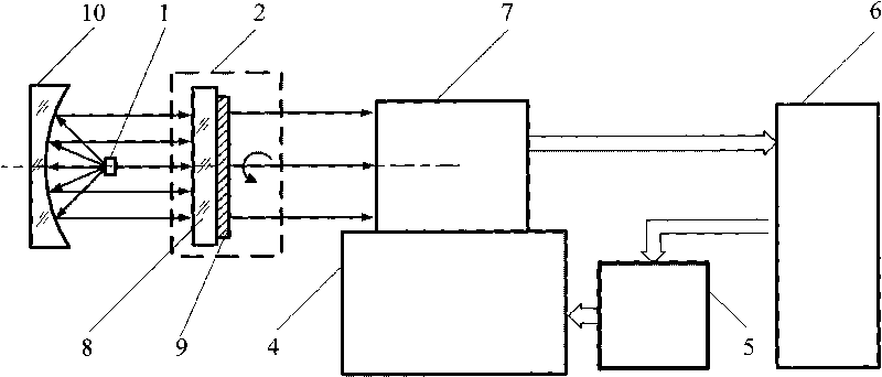
[0052] figure 2 It is the multi-spectral dynamic modulation transfer function measurement device described in the present invention, comprising a multi-spectral light source 1, a multi-spectral knife-edge reticle target plate 2, a parabolic reflector 10, a measured photoelectric imaging system 7, a vibration table 4, and a vibration controller 5 and computer 6; wherein the measured photoelectric imaging system 7 is fixed on the vibrating table 4, and the measured photoelectric imaging system 7 and the computer 6 are connected by a data transmission line; The photoelectric imaging system 7 is an infrared thermal imager.

[0053] The multi-spectral knife-edge reticle target plate 2 can be used in both visible light and infrared bands. The multi-spectral knife-edge reticle target plate 2 includes a two-layer structure, in which the ZnS substrate 8 can transmit light from visible light to long-wave infrared bands, and the chromium thin film layer 9 is plated On the area outside ...

Embodiment 2

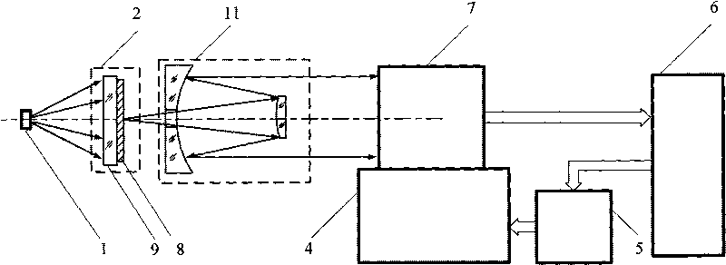
[0077] image 3 It is the multi-spectral dynamic modulation transfer function measuring device according to the present invention, comprising a multi-spectral light source 1, a multi-spectral knife-edge reticle target plate 2, an aspheric Cassegrain collimator 11, a measured photoelectric imaging system 7, and a vibration table 4 , a vibration controller 5 and a computer 6; wherein the photoelectric imaging system 7 under test is fixed on the vibration table 4, and the photoelectric imaging system 7 under test and the computer 6 are connected through a data transmission line; wherein the multispectral knife-edge demarcation target plate 2 adopts a multispectral light source 1. Illumination. The photoelectric imaging system 7 under test is a Microvision MVC930DAM-GE30 CCD with a pixel size of 4.65×4.65 μm and a resolution of 1024×1024.

[0078] The multi-spectral knife-edge reticle target plate 2 can be used in both visible light and infrared bands. The multi-spectral knife-edg...


PUM


Abstract

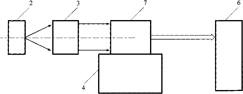
The invention belongs to the field of optical imaging test, more particularly to a method and a device for measuring a multispectral dynamic modulation transfer function, which can be used for a dynamic performance test of a composite photoelectronic imaging system. In the invention, a multispectral knife-edge division target plate is collimated by an collimating system and then imaged in a tested photoelectronic system fixed on a vibrating table, and modulation transfer functions under different conditions can be obtained after a knife-edge image obtained by the tested photoelectronic imaging system is processed by a computer and then calculated to obtain the tested dynamic modulation transfer function. By translating or rotating the multispectral knife-edge division target plate to simulate target motion and using the vibrating table to simulate the vibration of a weapon platform, the tested dynamic modulation transfer function is real and all-sided, can be used for estimating the dynamic performance of the composite photoelectronic imaging system under the actual service condition and has extremely important application prospect.

Description

technical field [0001] The invention belongs to the field of optical imaging testing, relates to a multi-spectral dynamic modulation transfer function measuring method and device, and can be used for dynamic performance testing of photoelectric imaging systems. technical background [0002] The modulation transfer function (MTF) of an optical system is a standard for objectively evaluating the imaging quality of an optical system. It fundamentally overcomes the shortcomings of traditional image quality inspection methods such as star point inspection, resolution, and geometric aberration. The imaging properties of the system play an important role in the evaluation of the imaging quality of the optical system. With the rapid development and application of photoelectric technology, photoelectric imaging and tracking systems have been widely used in various fields of the national economy, especially in the military field. When the photoelectric system is tracking the target, ...

Claims


Application Information

Patent Timeline
IPC IPC(8): G01M11/02
Inventor 赵维谦田丽黄旭沙定国邱丽荣
Owner BEIJING INSTITUTE OF TECHNOLOGYGY
Learn More