
Wind-power generator blade with multiple C-shaped structure

A technology of wind turbines and blades, which is applied in the field of wind rotor blades, which can solve the problems of increased blade weight and increased wind speed at fan startup, and achieve the effects of reducing tower weight, reducing manufacturing costs, and improving overall strength and stiffness

Inactive Publication Date: 2010-06-02
昆明理工峰潮科技有限公司
View PDF0 Cites 0 Cited by
  • Summary
  • Abstract
  • Description
  • Claims
  • Application Information

AI Technical Summary

Problems solved by technology

As a result, the weight of the blades increases, and the required start-up wind speed of the fan becomes larger

Method used


Image

  • Wind-power generator blade with multiple C-shaped structure
  • Wind-power generator blade with multiple C-shaped structure
  • Wind-power generator blade with multiple C-shaped structure

Examples


Embodiment 1

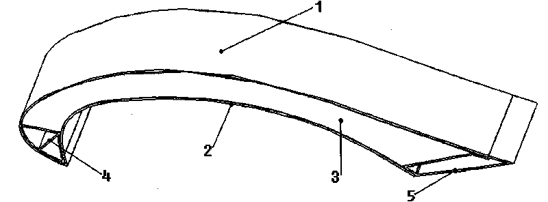
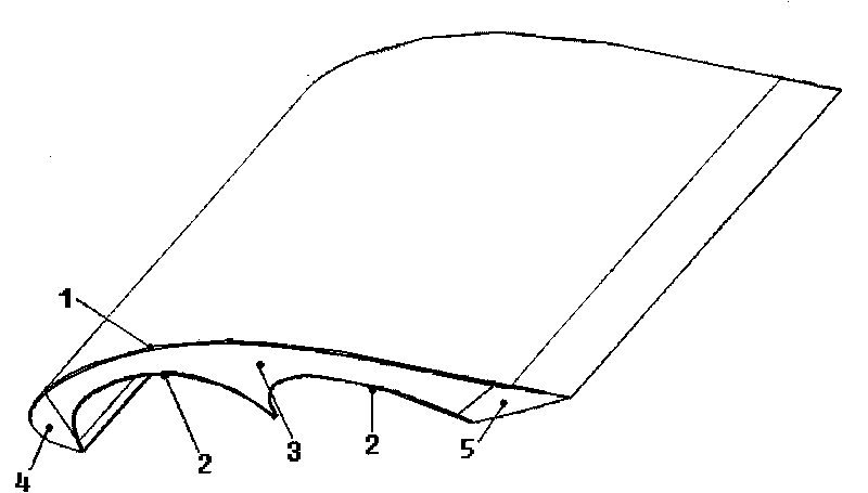
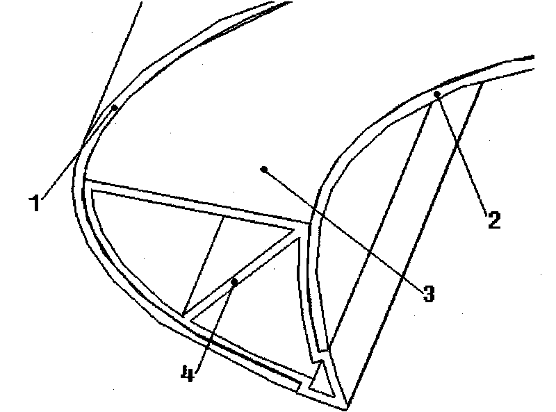
[0017] Vertical axis multiple C-shaped structure wind turbine blades. First, the honeycomb aluminum plate with a thickness of 3-4 mm and a length of 12 m is prepared into the required inner and outer C-shaped shells of the blade according to the design requirements, forming the outer C-shaped plate shell 1 and the inner C-shaped plate shell 2 . Then according to the design requirements, the 3mm aluminum plate is plastically deformed and punched into the designed shape to form the profile support body 3, and the inner C-shaped plate shell 2 and the support body 3 are respectively fixed. Finally, the outer C-shaped plate shell 1 and the inner C-shaped plate shell 2 are connected by using the streamlined splitter head 4 and the flex fin 5 to prepare a wind turbine blade with a vertical axis multi-C-shaped structure. The wind rotor blades prepared by this scheme have good streamline shape and high wind energy conversion efficiency. Under the premise of meeting the mechanical prope...

Embodiment 2

[0019] Horizontal axis multiple C-shaped structure wind turbine blades. First, a metal stainless steel plate with a thickness of 3 to 4mm and a length of 12m is prepared into the required inner and outer C-shaped plate shells of the blade according to the design requirements (decreasing with a gradient of 1:5), forming the outer C-shaped plate shell 1 and the inner plate shell. C-shaped plate shell 2. Then according to the design requirements, the 3mm aluminum plate is plastically deformed and stamped into a designed shape to form a profile support body 3, and the inner C-shaped plate shell 2 and the support body 3 are respectively fixed. Finally, the outer C-shaped plate shell 1 and the inner C-shaped plate shell 2 are connected by the streamlined splitter 4 and the deflector fin 5 to form a single horizontal axis multi-C-shaped wind turbine blade, and the three blades are connected to form a length of 36.5m horizontal axis multiple C-shaped wind turbine blades. The wind ro...


PUM


Abstract

The invention relates to a rotor blade of a wind-power generator, in particular to a rotor blade of a large-scale wind-power generator. The main contour of the rotor blade comprises two or more C-shaped shells; the outer C-shaped shell is an aerodynamic wing-shaped curve; and the inner C-shaped shell is an arc curve. By adopting the multiple C-shaped shell structure, the blade simultaneously has the advantages of a lifting-type blade and a resistance-type blade, realizes low start wind speed, high wind-electricity conversion efficiency and stronger suitability and utilizes an arc shunt head and a tail wing to connect a plurality of inner and outer C-shaped shells into the wind-power generator blade in the closed structure. The invention has the advantages of simple structure, light weight, low start wind speed, high wind-electricity conversion efficiency and low manufacture and maintenance costs.

Description

technical field [0001] The invention relates to a wind rotor blade of a wind power generator, in particular to a wind rotor blade of a large wind power generator suitable for starting at low wind speed. technical background [0002] Compared with traditional power generation, wind power generation is a pollution-free power generation method. In recent years, the wind power industry has developed rapidly, and the installed capacity of wind power in countries around the world is increasing day by day. According to the statistics of the World Wind Energy Association, as of December 31, 2005, the world's installed capacity has reached 58,982MW, 11,310MW more than in 2004. At present, wind power generation accounts for 1% of the global electricity generation, and some countries and regions have reached 20% or more. [0003] Existing wind power generators are divided into two categories: horizontal axis wind power generators and vertical axis wind power generators. The cross-se...

Claims


Application Information

Patent Timeline
Patent Type & Authority Applications(China)
IPC IPC(8): F03D1/06F03D3/06
CPCY02E10/72Y02E10/721Y02E10/74Y02P70/50
Inventor 孙勇彭明军王跃宗潘志强
Owner 昆明理工峰潮科技有限公司
Learn More