Operational amplifier circuit and display apparatus
A technology of an operational amplifier circuit and amplifying part, which is applied to amplifiers, differential amplifiers, and improved amplifiers to reduce temperature/power supply voltage changes, etc. The effect of reducing the area, suppressing the increase of the circuit area, and reducing the output voltage deviation
- Summary
- Abstract
- Description
- Claims
- Application Information
AI Technical Summary
Problems solved by technology
Method used
Image
Examples
Embodiment 1
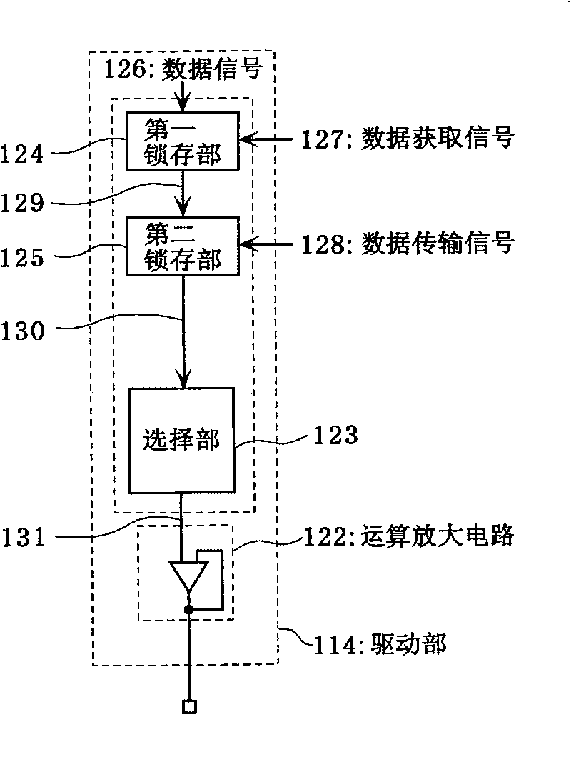
[0103] In Embodiment 1 of the present invention, for figure 2 One embodiment of operational amplifier circuit 122 is shown as operational amplifier circuit 122A for illustration.
[0104] Figure 4 It is a diagram for comparison, and is a circuit diagram of a general operational amplifier circuit 222 .
[0105] Figure 4 The illustrated operational amplifier circuit 222 is an operational amplifier having inverting and non-inverting input terminals and an output terminal Vout.
[0106] The inverting input terminal is connected to the output terminal Vout. Accordingly, the operational amplifier circuit 222 outputs the voltage value applied to the non-inverting input terminal to the output terminal Vout.
[0107] This operational amplifier circuit 222 has a differential amplification unit 31 (differential stage) and an output unit 32 (output stage).
[0108] The differential amplifier 31 amplifies the voltage difference between the voltage of the inverting input terminal an...
Embodiment 2
[0179] In embodiment 2 of the present invention, for figure 2 One embodiment of operational amplifier circuit 122 is shown, operational amplifier circuit 122B, for illustration.
[0180] Figure 9 It is a circuit diagram of the operational amplifier circuit 122B according to the second embodiment of the present invention. And, for Figure 5 The same elements are assigned the same symbols, and repeated explanations are omitted here.
[0181] Figure 9 The operational amplifier circuit 122B is shown with Figure 5 In contrast to the configuration of the illustrated operational amplifier circuit 122A, a variable resistance unit 15B is provided instead of the variable resistance unit 15A. This variable resistance unit 15B has a variable resistance element 21 and a correction polarity switching circuit 61 .
[0182] The variable resistance element 21 is connected between the source of the differential transistor 100 on the non-inverting input side and the source of the diffe...
Embodiment 3
[0230] In Embodiment 3 of the present invention, for figure 2 One embodiment of operational amplifier circuit 122 is shown as operational amplifier circuit 122C for illustration.
[0231] Figure 12 is a circuit diagram of an operational amplifier circuit 122C according to Embodiment 3 of the present invention. For with Figure 5 The same symbols are given to the same elements, and repeated explanations are omitted.
[0232] Figure 12 The operational amplifier circuit 122C shown in addition has Figure 5 In addition to the configuration of the operational amplifier circuit 122A shown, variable current sources 81 and 82 are included.
[0233] The variable current source 81 is connected between the source of the differential transistor 100 on the non-inverting input side and a bias voltage, and supplies positive or negative current Icp to the source of the differential transistor 100 on the non-inverting input side. Furthermore, the variable current source 81 selectively...
PUM
 Abstract
Description
Claims
Application Information
 - R&D Engineer
- R&D Manager
- IP Professional
- Industry Leading Data Capabilities
- Powerful AI technology
- Patent DNA Extraction
Browse by: Latest US Patents, China's latest patents, Technical Efficacy Thesaurus, Application Domain, Technology Topic, Popular Technical Reports.
© 2024 PatSnap. All rights reserved.Legal|Privacy policy|Modern Slavery Act Transparency Statement|Sitemap|About US| Contact US: help@patsnap.com


