Current forecasting dead-beat control method of Z source type interconnected inverter and control device thereof
A dead-beat control and current prediction technology, applied in the direction of output power conversion device, AC power input conversion to DC power output, electrical components, etc., to achieve the effect of overcoming sampling delay
- Summary
- Abstract
- Description
- Claims
- Application Information
AI Technical Summary
Problems solved by technology
Method used
Image
Examples
specific Embodiment approach 1
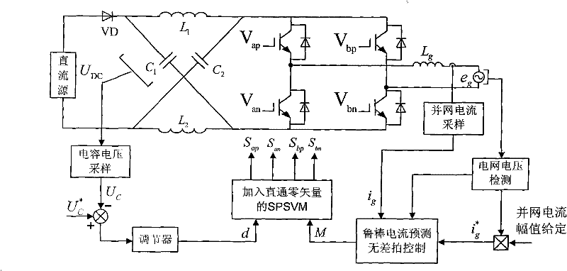
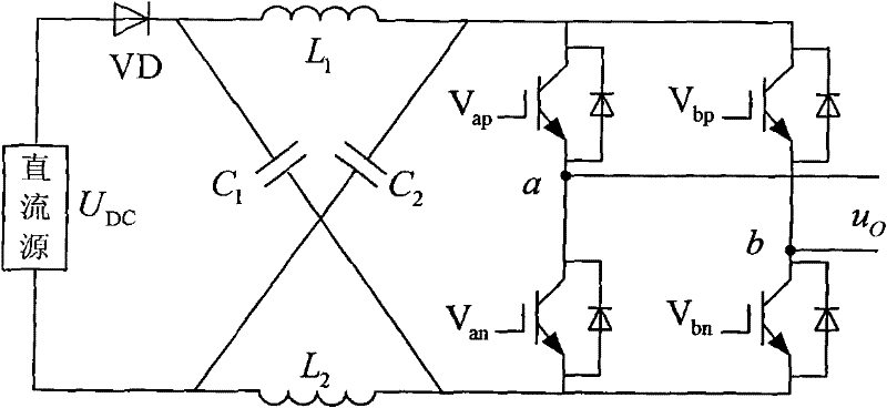
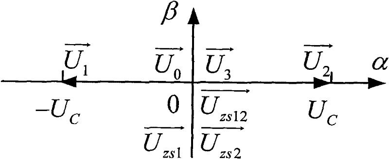
[0011] Specific implementation mode one: the following combination figure 1 This embodiment will be described concretely through FIG. 6 . The control method of this embodiment includes the following steps: its control method includes the following steps: 1. Collect the grid-connected current and grid voltage signal at the sampling time point of each sampling period; 2. Collect the grid voltage phase and calculate its The sine value is multiplied by the given grid-connected current amplitude to obtain the instantaneous value of the given signal of the grid-connected current at the sampling time point synchronous with the grid voltage; 3. According to the voltage and current signals obtained in step 1, the next The instantaneous value of the grid-connected current at the sampling time point; 4. Bring the calculation results of steps 2 and 3 into the voltage equation of the grid-connected inverter to calculate the given value of the output voltage of the Z-source inverter at the ...
specific Embodiment approach 2
[0056] Specific implementation mode two: the following combination Figure 7 This embodiment will be specifically described. The current prediction dead-beat control device of the Z-source grid-connected inverter consists of a grid-connected current detection circuit 1, a grid voltage detection circuit 2, a synchronous signal generation circuit 3, an isolation drive circuit 4, a central processing unit 5 and a capacitor voltage detection circuit. 6 components, the signal output terminal of the grid-connected current detection circuit 1 is connected to a signal input terminal of the central processing unit 5 to realize the sampling of the grid-connected current value, and the output terminal of the grid voltage detection circuit 2 is connected to the second signal of the central processing unit 5 The input terminal is to realize the sampling of the grid voltage signal, the output terminal of the grid voltage detection circuit 2 is also connected with the signal input terminal o...
PUM
 Abstract
Description
Claims
Application Information
 - R&D Engineer
- R&D Manager
- IP Professional
- Industry Leading Data Capabilities
- Powerful AI technology
- Patent DNA Extraction
Browse by: Latest US Patents, China's latest patents, Technical Efficacy Thesaurus, Application Domain, Technology Topic, Popular Technical Reports.
© 2024 PatSnap. All rights reserved.Legal|Privacy policy|Modern Slavery Act Transparency Statement|Sitemap|About US| Contact US: help@patsnap.com


