
Electronic ballast and fluorescent lamp device

An electronic ballast and fluorescent lamp technology, applied in the field of fluorescent lamps, can solve the problems of short service life and low luminous flux maintenance rate of fluorescent lamps, and achieve the effects of improving luminous flux maintenance rate, improving utilization rate and prolonging service life

Inactive Publication Date: 2013-09-04
OCEANS KING LIGHTING SCI&TECH CO LTD +1
View PDF4 Cites 0 Cited by
  • Summary
  • Abstract
  • Description
  • Claims
  • Application Information

AI Technical Summary

Problems solved by technology

[0004] The purpose of the embodiments of the present invention is to provide an electronic ballast, aiming to solve the problems of short service life and low lumen maintenance rate of existing fluorescent lamps

Method used


Image

  • Electronic ballast and fluorescent lamp device
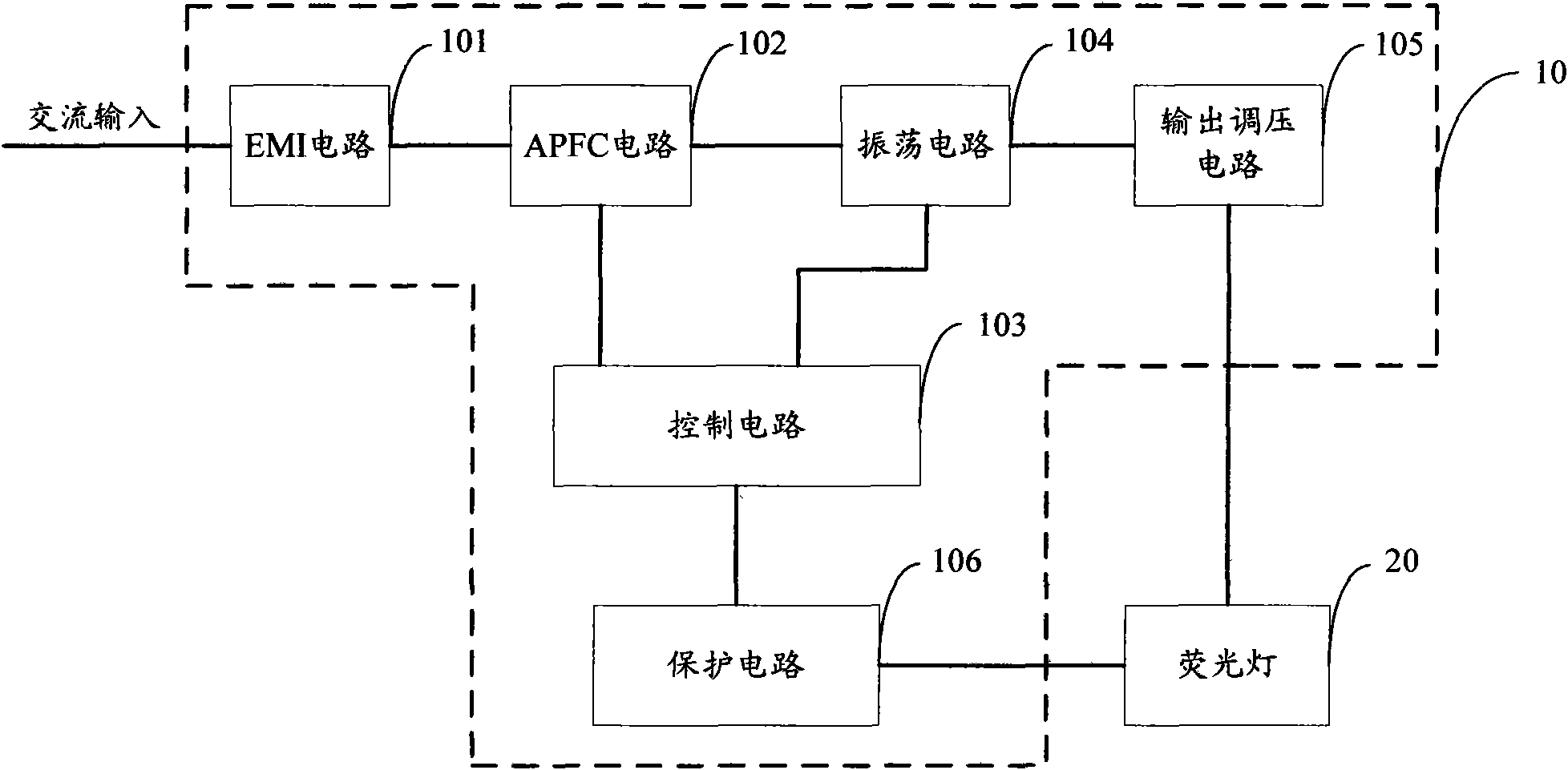
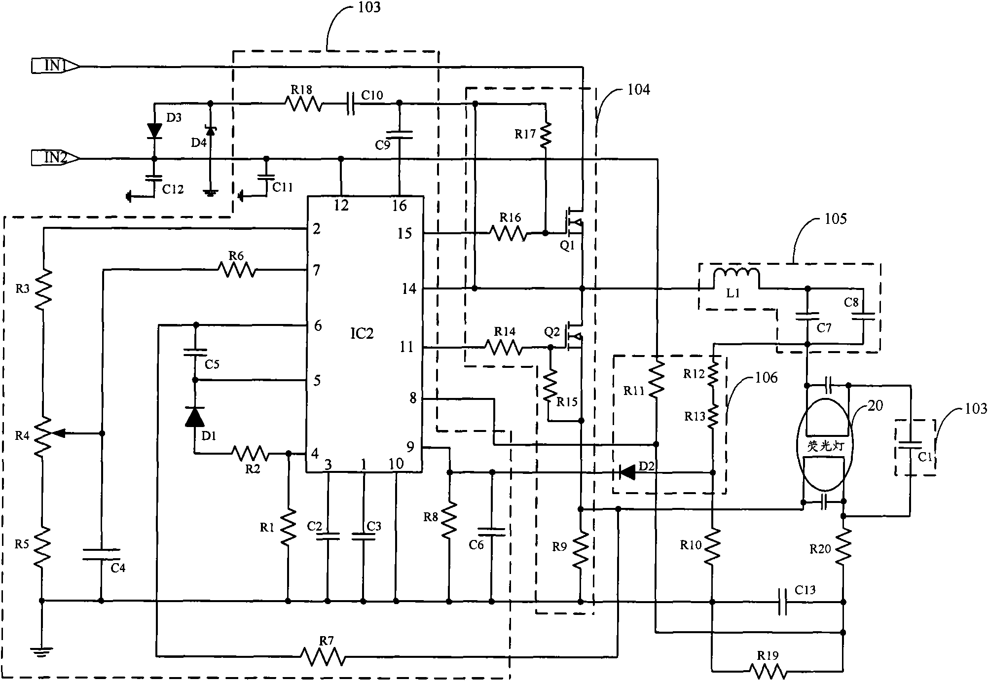
  • Electronic ballast and fluorescent lamp device
  • Electronic ballast and fluorescent lamp device

Examples


Embodiment Construction

[0021] In order to make the object, technical solution and advantages of the present invention clearer, the present invention will be further described in detail below in conjunction with the accompanying drawings and embodiments. It should be understood that the specific embodiments described here are only used to explain the present invention, not to limit the present invention.

[0022] The electronic ballast provided by the embodiment of the present invention uses a control circuit to control the preheating time, preheating frequency and ignition time of the filament of the fluorescent lamp, prolonging the service life of the fluorescent lamp and improving the luminous flux maintenance rate.

[0023] The electronic ballast 10 provided by the embodiment of the present invention is mainly used in fluorescent lamp devices to drive the fluorescent lamp 20 to work; wherein, the module structure of the electronic ballast 10 is as follows figure 1 As shown, for ease of descriptio...


PUM


Abstract

The invention is applicable to the field of fluorescent lamps, and provides an electronic ballast and a fluorescent lamp device. The electronic ballast comprises an EMI circuit, an APFC circuit and an oscillating circuit which are connected in sequence, and also comprises a controlling circuit, an output voltage regulating circuit and a protection circuit; before a fluorescent lamp is turned on, the controlling circuit controls the filament of the fluorescent lamp to be preheated; after the preheating, the controlling circuit controls the fluorescent lamp to be turned on; when the fluorescent lamp works normally, the controlling circuit regulates the operating current of the fluorescent lamp to realize light regulating control. The electronic ballast adopts the controlling circuit to control the preheating time, the preheating frequency and the turn-on time of the filament of the fluorescent lamp, prolongs the service life of the fluorescent lamp, and improves the lumen maintain; in addition, the electronic ballast can also perform light regulation control, improves the energy utilization rate, and is energy-saving and environment-friendly.

Description

technical field [0001] The invention belongs to the field of fluorescent lamps, in particular to an electronic ballast and a fluorescent lamp device. Background technique [0002] Fluorescent lamps driven by electronic ballasts are widely used due to their high luminous efficiency, energy saving and environmental protection; however, the existing fluorescent lamps generally use cold start, because the filament impedance of fluorescent lamps is extremely low, so the instantaneous current generated is very large , has a great impact on the life of electronic ballasts and fluorescent lamp tubes, and at the same time has a low luminous flux maintenance rate. [0003] Fluorescent lamps in the prior art also have a preheating design, but lack of intelligent control of the preheating time and preheating current, which will also reduce the service life of the fluorescent lamp tube. Contents of the invention [0004] The purpose of the embodiments of the present invention is to pr...

Claims


Application Information

Patent Timeline
Patent Type & Authority Patents(China)
IPC IPC(8): H05B41/232H05B41/298H05B41/392
Inventor 周明杰谢万源
Owner OCEANS KING LIGHTING SCI&TECH CO LTD
Learn More