
Constant-current constant-voltage charging circuit

A constant-voltage charging and circuit technology, which is applied in the direction of battery circuit devices, circuit devices, collectors, etc., can solve the problem that the charging circuit cannot meet the charging needs of large-capacity and high-voltage equipment

Active Publication Date: 2010-05-12
雷智数系统技术西安有限公司
View PDF0 Cites 2 Cited by
  • Summary
  • Abstract
  • Description
  • Claims
  • Application Information

AI Technical Summary

Problems solved by technology

[0004] The purpose of the present invention is to solve the problem that the existing charging circuit cannot meet the charging requirements of large-capacity and high-voltage equipment

Method used


Image

  • Constant-current constant-voltage charging circuit
  • Constant-current constant-voltage charging circuit
  • Constant-current constant-voltage charging circuit

Examples


Embodiment Construction

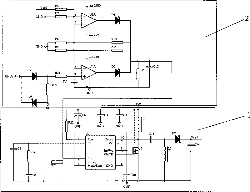
[0023] see figure 1 , The constant current and constant voltage charging circuit of the present invention mainly includes a boost switch circuit 1 and a detection circuit 2 connected to the boost switch circuit 1 for detecting the current and voltage of the accumulator.

[0024] see figure 2 , the composition of the detection circuit 2 of the present invention and its electrical connection relationship are:

[0025] One end of the first resistor R1 is connected to the non-inverting input end of the first integrated operational amplifier U1A, and the other end is connected in series to one end of the accumulator;

[0026] The second resistor R2 is connected in series between the ground and the non-inverting input terminal of the first integrated operational amplifier U1A;

[0027] The third resistor R3 is connected in series between the ground and the inverting input terminal of the first integrated operational amplifier U1A;

[0028] The fourth resistor R4 is connected in ...


PUM


Abstract

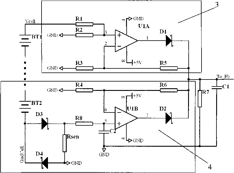
The invention relates to a constant-current constant-voltage charging circuit which comprises an accumulator, a switch booster circuit and a detection circuit which is connected with the switch booster circuit and used for detecting the charging current and voltage of the accumulator; the constant-current constant-voltage charging circuit comprises the following steps: amplifying detection signals of the voltage and current of the accumulator, then superposing the detection signals by a first isolation diode D1 and a second isolation diode D2, forming control signals To_Fb of a switch booster power supply, and further controlling the feedback quantity of the switch booster circuit, thus realizing the regulation of the charging voltage of the accumulator and the constant current and voltage charging of the accumulator with high capacity and high voltage.

Description

technical field [0001] The invention relates to a charging circuit, in particular to a constant current and constant voltage charging circuit. Background technique [0002] When many electrical storage devices are in a low voltage state, the charging current will be very large. If there is no limit, the charging device will be damaged; in addition, if the charging voltage exceeds the voltage limit of the electrical storage device, the electrical storage device will be damaged. In order to charge the storage device quickly, when the device is in a low voltage state, the constant current method is generally used for charging; when the voltage of the storage device is close to the limit voltage, the constant voltage method is generally used for charging to make the device reach a saturated state. [0003] Existing charging chips and circuits are mainly designed for batteries, and their limited voltage and charging current are only effective within a certain range. It is difficu...

Claims


Application Information

Patent Timeline
Patent Type & Authority Applications(China)
IPC IPC(8): H02J7/00
Inventor 刘升史宝祥
Owner 雷智数系统技术西安有限公司
Learn More