Electric flange turner

A flanging machine, electric technology, applied in the direction of metal processing equipment, feeding devices, manufacturing tools, etc., can solve the problems of unreliable quality, falling off of pipes and flanges, high cost, etc., and achieve rapid mass production and uniform circumferential direction , the effect of simple structure

Active Publication Date: 2011-08-24
厦门中井科技有限公司
View PDF3 Cites 0 Cited by
  • Summary
  • Abstract
  • Description
  • Claims
  • Application Information

AI Technical Summary

Problems solved by technology

[0006] ④Expand the end of the pipe to an angle of 30-50° with a flanging tool or flaring tool, then place the 90° right-angle extrusion head against the expansion port, and turn the end face to 90° with the help of an electric pressing tool or a manual tool Corner, this kind of processing is time-consuming and laborious, and the processing quality is often not guaranteed, and the width of the flange is often inconsistent. The length of the basic conveying pipe with flange (flange) is limited by the tool, and the length is only about ten centimeters
However, there are the following disadvantages: the weld is generally welded on one side, the inner and outer walls cannot be formed on both sides, and the welding quality is unreliable; it must be a skilled worker, and the cost is high; the product connection must be carried out on the construction site, and generally the cutting and welding of the pipeline are required , removal of welding slag, pickling, passivation and anti-corrosion treatment, etc., often the construction site basically cannot meet the above process requirements, and corrosion will start from the welding joint in the future, and the welding joint is prone to rust
The site generally does not have pipeline welding spot testing equipment. If the welding quality is poor, the pipe and flange will fall off under the pressure flow state.

Method used


Image

  • Electric flange turner
  • Electric flange turner
  • Electric flange turner

Examples


Embodiment Construction

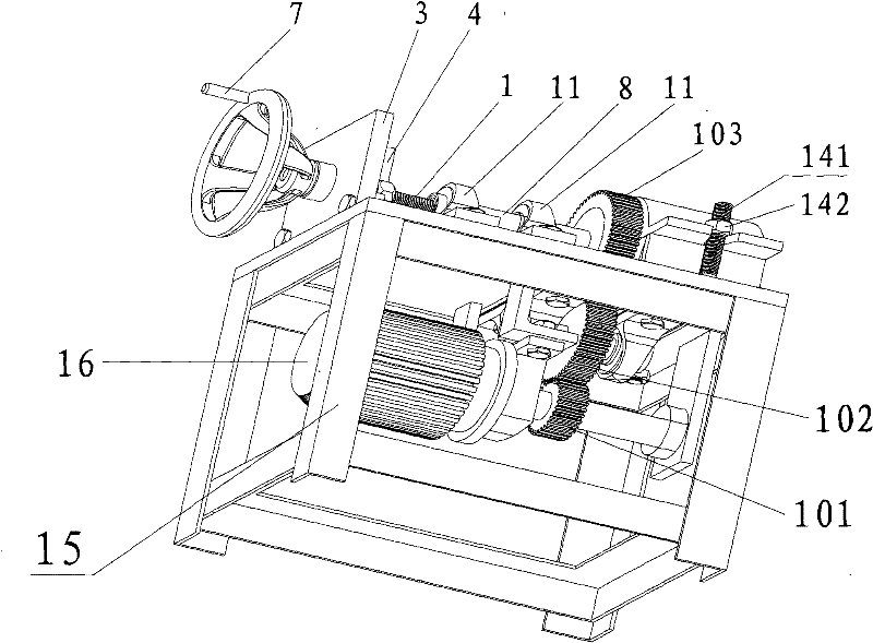
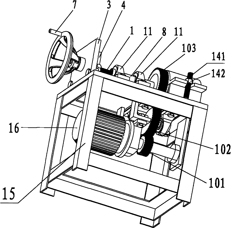
[0026] see figure 1 and 2 , the present invention is provided with frame 15, feeding device and clamp, and feeding device and clamp are located on frame 15.

[0027] Frame 15 is provided with 4 legs and table top, adopts angle steel to weld.

[0028] The feeding device is provided with a motor 16, a gear transmission mechanism, a rotating roller 8, flanging balls 2 (3 pieces) and a propelling rod 1. Motor 16 is installed on the frame 15, and the output shaft front end of motor 16 is supported on the frame 15 by bearing 13, and transmission mechanism is provided with first gear 101, second gear 102 and the 3rd gear 103, and first gear 101 and motor 16 The output shaft is connected, the first gear 101 meshes with the second gear 102, the gear shaft 5 of the second gear 102 is installed through the seat bearing 9, the second gear 102 meshes with the third gear 103, and the third gear 103 is sleeved on the rotating roller 8 on. The rotating roller 8 is installed on the frame 1...


PUM


Abstract

The invention discloses an electric flange turner which relates to flange turning equipment. The invention provides an electric flange turner which is free from the influence of a construction environment at any place, is free from the limitation of the length of a transmission pipe, provided with a flange, a turning edge on the end surface of a pipe, wherein the flange and the turning edge also can be integrated into a whole. The electric flange turner is provided with a frame, a feed device and a clamp, wherein the feed device is provided with a motor, a drive mechanism, a rotating roller, a flange turning ball and a push rod; the motor is connected with the drive mechanism, and the drive mechanism is connected with the rotating roller; the rotating roller is provided with a ball guide groove; the front end of the rotating roller is provided with a wedge head; the flange turning ball is positioned in the ball guide groove; a shaft axis at the front end of the ball guide groove is obliquely crossed with a rotating shaft axis of the rotating roller; the front end of the push rod is positioned in the rear end of the ball guide groove of the rotating roller, and the rear end of the push rod is provided with a handle; the clamp is provided with an upper cover and a lower cover, and the upper cover and the lower cover are butted; a pipe holding hole, a pipe clamping hoop and a pipe clamping hoop groove are arranged between the upper cover and the lower cover, and the pipe clamp is embedded into the pipe clamping hoop groove; the pipe clamping hoop groove and the pipe holding hole are coaxial, and the clamp faces to the front end of the rotating roller.

Description

technical field [0001] The invention relates to a flanging device, in particular to an electric flanging machine for forming a flange or flanging on the end face of a pipe. Background technique [0002] In practical applications, in order to facilitate the disassembly and assembly of pipes and meet the requirements of connection strength and sealing performance, it is often necessary to flang the end faces of pipes, and the flanging can be directly used as flanges (the two pipes to be connected The flanging can be directly welded or bolted holes can be connected with bolts), and it can also be used in conjunction with a loop-type movable flange (the movable flange is set on the pipe and pressed against one side of the welded flange sub-joint) . Existing flanging equipment has advantages and disadvantages respectively. In the prior art, there are generally the following methods for realizing the 90° angle of the end face (flange) of the pipe: [0003] ① Make the concave lo...

Claims


Application Information

Patent Timeline
Patent Type & Authority Patents(China)
IPC IPC(8): B21D19/12B21D43/00
Inventor 陈荣辉
Owner 厦门中井科技有限公司
Why Eureka
Try Eureka