
Special mechanism for automatically conveying high-temperature saw bit

A kind of mechanical device, technology of saw blade

Active Publication Date: 2010-04-28
NANJING UNIV OF SCI & TECH
View PDF0 Cites 14 Cited by
  • Summary
  • Abstract
  • Description
  • Claims
  • Application Information

AI Technical Summary

Problems solved by technology

At present, there is no relevant automatic transmission device for high-temperature saw blades in the open domestic and foreign literature.

Method used


Image

  • Special mechanism for automatically conveying high-temperature saw bit
  • Special mechanism for automatically conveying high-temperature saw bit
  • Special mechanism for automatically conveying high-temperature saw bit

Examples


Embodiment Construction

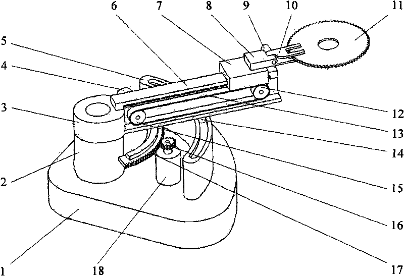
[0012] to combine figure 1 , the special mechanical device for automatic transmission of high-temperature saw blades of the present invention, including a base 1, a column 2, a rotating horizontal frame 3, a sliding drive motor 4, a rotating guide rail 5, a sliding guide rail 6, a slider 7, a clamping and fixing block 8, and a clamping drive Motor 9, movable claw 10, driven pulley 12, conveyor belt 13, positioning pin 14, driving pulley 15, pinion 16, circular arc rack 17, rotating drive motor 18 etc. Wherein, the column 2 is fixed on the base 1, the rotating horizontal frame 3 is connected with the column 2 and can rotate around the column 2, the sliding driving motor 4 is fixed on the rotating horizontal frame 3, and the output shaft of the sliding driving motor 4 is equipped with a driving pulley 15. The driving pulley 15 and the driven pulley 12 fixed on the rotating horizontal frame 3 realize synchronous transmission through the conveyor belt 13, thereby driving the slide...


PUM


Abstract

The invention discloses a special mechanism for automatically conveying a high-temperature saw bit. The mechanism comprises a base, an upright post and the like, wherein the upright post is fixed on the base, a rotating crossarm is connected with the upright post and can rotate around the upright post, and a slider fixed on a conveyer belt is driven to move on a sliding guide rail by a sliding driving motor which is fixed on the rotating corssarm through pulley transmission; actions of a movable paw of clamping and loosening a high-temperature sheet are realized through the rotation of a clamping driving motor fixed on the slider; and the rotating driving motor is fixed on the base, an output shaft is provided with a pinion which is meshed with a circular arc rack fixed on the rotating crossarm to drive the rotating crossarm to rotate around the upright post, and a positioning pin on the rotating corssarm slides on the rotating guide rail during rotating so as to realize the function of rotatably conveying the high-temperature saw bit. The mechanism can realize the high-speed high-efficiency conveying of the high-temperature saw bit, eliminates adverse influence such as the pressing precision reduction and quality reduction of the saw bit caused by overlarge temperature drop in the conveying process, and has the advantages of high efficiency, high speed, accuracy and reliability.

Description

technical field [0001] The invention relates to a special device for clamping and automatically transporting high-temperature saw blades, in particular to a special mechanical device for high-speed automatic transmission of high-temperature saw blades on a saw blade forming and processing production line. Background technique [0002] In the process of saw blade pressing and forming, it is necessary to be able to accurately transfer the saw blade heated to a specific high temperature (840°C) from the outlet of the heating resistance furnace to the worktable of the press, and then the press presses the high temperature saw blade Press to ensure that the saw blade is flat and smooth. In the saw blade production line, the press is generally arranged at a position of about 1.0 meters from the outlet of the resistance furnace to ensure an independent transmission space for the saw blade body (the circular size of the saw blade is generally below Φ600mm). [0003] In the process ...

Claims


Application Information

Patent Timeline
IPC IPC(8): B23D65/00B25J9/00
Inventor 冯虎田陶卫军欧屹李春梅韩军殷爱华孔振
Owner NANJING UNIV OF SCI & TECH
Learn More