
Domestic appliance with a self-diagnosing door lock position detection device

A technology for household appliances and detection devices, which can be used in measuring devices, washing devices, cleaning devices, etc., and can solve problems such as inability to be identified.

Active Publication Date: 2010-03-31
BOSCH SIEMENS HAUSGERATE GMBH
View PDF0 Cites 15 Cited by
  • Summary
  • Abstract
  • Description
  • Claims
  • Application Information

AI Technical Summary

Problems solved by technology

[0004] The disadvantage of these types of reed switches is that faults due to short circuits or interruptions will be interpreted and assumed to be normal conditions and thus cannot be identified

Method used


Image

  • Domestic appliance with a self-diagnosing door lock position detection device
  • Domestic appliance with a self-diagnosing door lock position detection device

Examples


Embodiment Construction

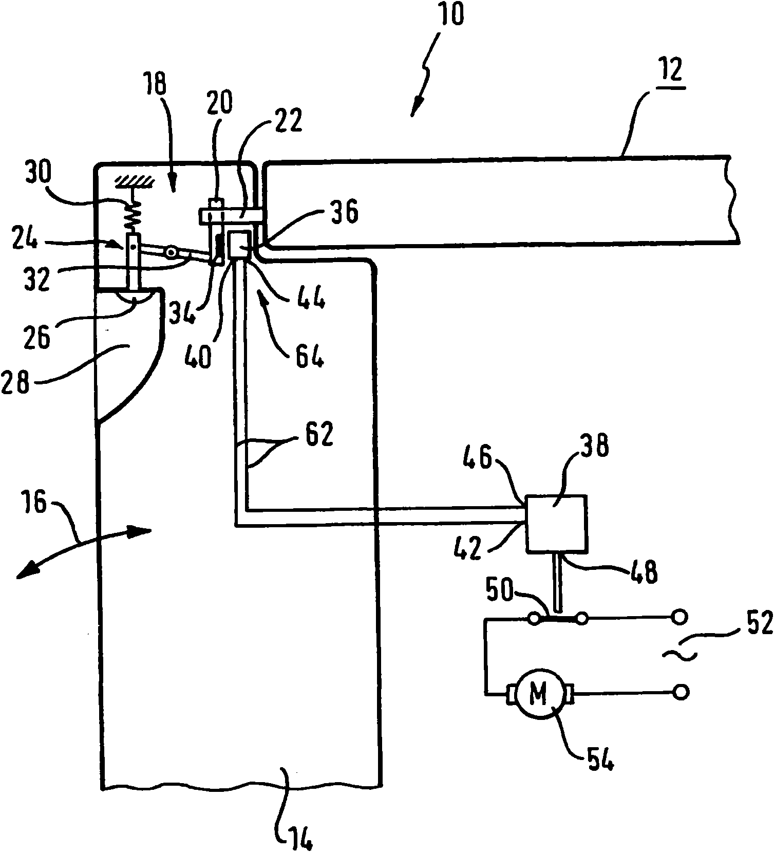
[0027] figure 1 A schematic diagram of a portion of dishwasher 10 is shown. The dishwasher 10 has a housing 12 which can be closed by a door 14 . Door 14 is hinged to housing 12 such that it can be opened or closed in the direction indicated by double-headed arrow 16 , respectively. The layout and method of operation of the dishwasher 10 are generally known and, therefore, these are not discussed in any further detail in this specification.

[0028] The door 14 can be latched on the housing 12 by means of a closure device 18 . The closing device 18 includes a door lock striker 20 which can snap-fit ​​with a latch 22 . The locking member 22 is disposed on the housing 12 and is snap-fitted into a corresponding opening (not shown) of the door 14 . The door lock striker 20 can be moved by means of an actuating device 24 . The actuation device 24 includes a button element 26 accessible via a recessed handle 28 in the door 14 . The pushbutton element 26 can be displaced agains...


PUM


Abstract

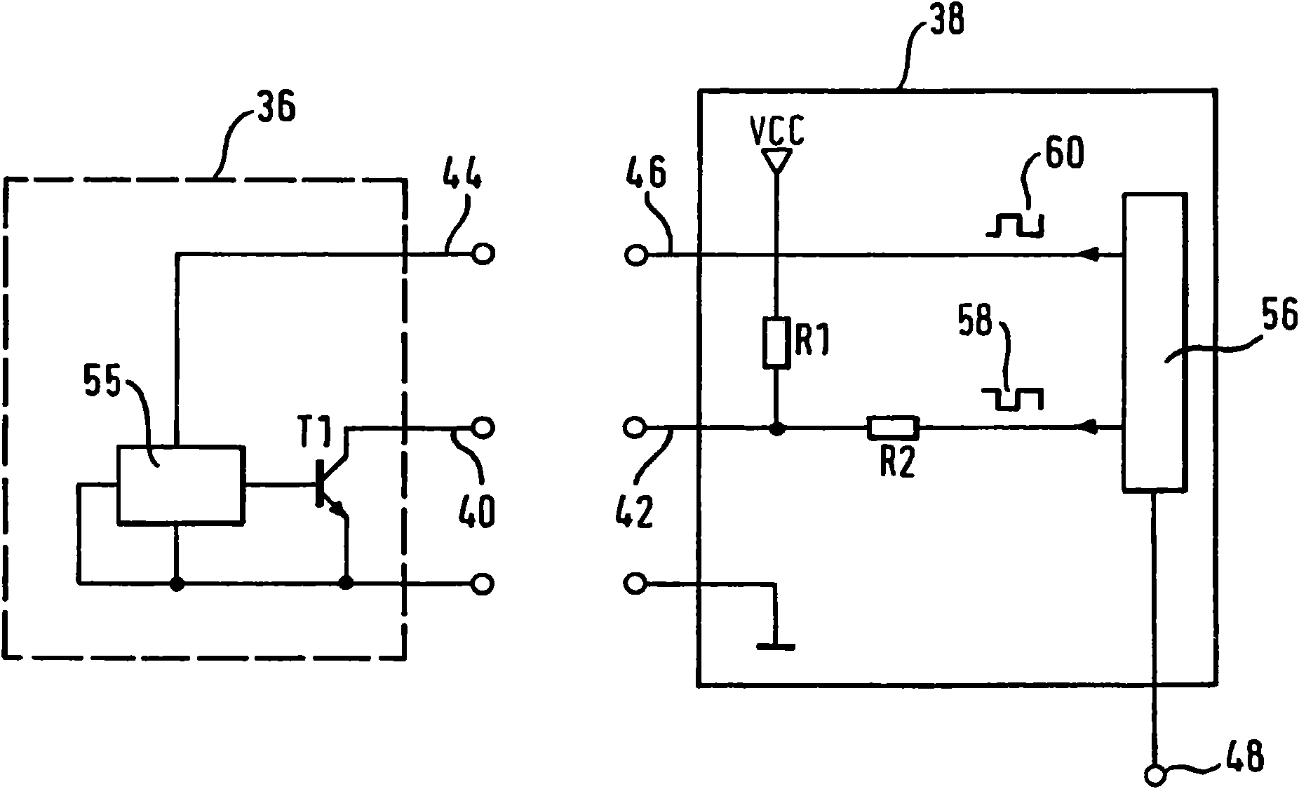
The invention relates to a domestic appliance (10) having a door (14) which can be arrested by means of a locking device (18), and having a door lock position detection device (64) which has at least one permanent magnet (34) and a magnetic switch which can be moved to the active range of the permanent magnet (34) by movement of the door (14). The invention provides for the magnetic switch to be a Hall sensor (36). The invention also covers a door lock position detection device (64).

Description

technical field [0001] The invention relates to a household appliance as stated in the preamble of claim 1 . Background technique [0002] Household appliances of the general type are well known. Therefore, it is necessary to detect the door lock position of the household appliance to ensure the safe operation of the household appliance. For example, in a dishwasher, if the door is no longer closed, the recirculation pump stops. This is designed to avoid burns due to the spray of water. [0003] It is known that the door lock position can be detected by using a reed switch. A reed switch includes magnetizable switch contacts disposed in a protected enclosure that are moved to a closed or open position by an external permanent magnet. A permanent magnet is provided on the movable closure part of the door lock. If the door lock is now opened, the reed switch moves out of range of the permanent magnet. Depending on the circuit, this opens or closes the reed switch, and ch...

Claims


Application Information

Patent Timeline
Patent Type & Authority Applications(China)
IPC IPC(8): A47L15/42D06F37/42G01R33/07
CPCG01D3/08A47L2501/05G01R33/07A47L2401/26A47L15/4259A47L2401/30G01D5/145
Inventor J·克里斯特曼P·施魏尔
Owner BOSCH SIEMENS HAUSGERATE GMBH
Learn More