
Optical information recording method, optical information recording medium, optical information reproducing device, optical information reproducing method, and optical information recording and reprod

A technology of optical information and recording method, which is applied in the direction of optical recording/reproduction/erasing method, optical recording/reproduction, optical recording carrier, etc., which can solve the problems of low light beam sensitivity and low recording speed, and achieve enhanced Effect of recording speed, good information reproduction performance

Inactive Publication Date: 2010-03-24
SONY GRP CORP
View PDF1 Cites 7 Cited by
  • Summary
  • Abstract
  • Description
  • Claims
  • Application Information

AI Technical Summary

Problems solved by technology

[0006] However, the optical information recording medium having such a configuration has a problem that the sensitivity to the light beam is low, and the light beam must be irradiated for a long time in order to form a recording mark, whereby the recording speed is low.

Method used


Image

  • Optical information recording method, optical information recording medium, optical information reproducing device, optical information reproducing method, and optical information recording and reprod
  • Optical information recording method, optical information recording medium, optical information reproducing device, optical information reproducing method, and optical information recording and reprod
  • Optical information recording method, optical information recording medium, optical information reproducing device, optical information reproducing method, and optical information recording and reprod

Examples


no. 1 approach

[0039] 2.1. Structure of optical information recording medium

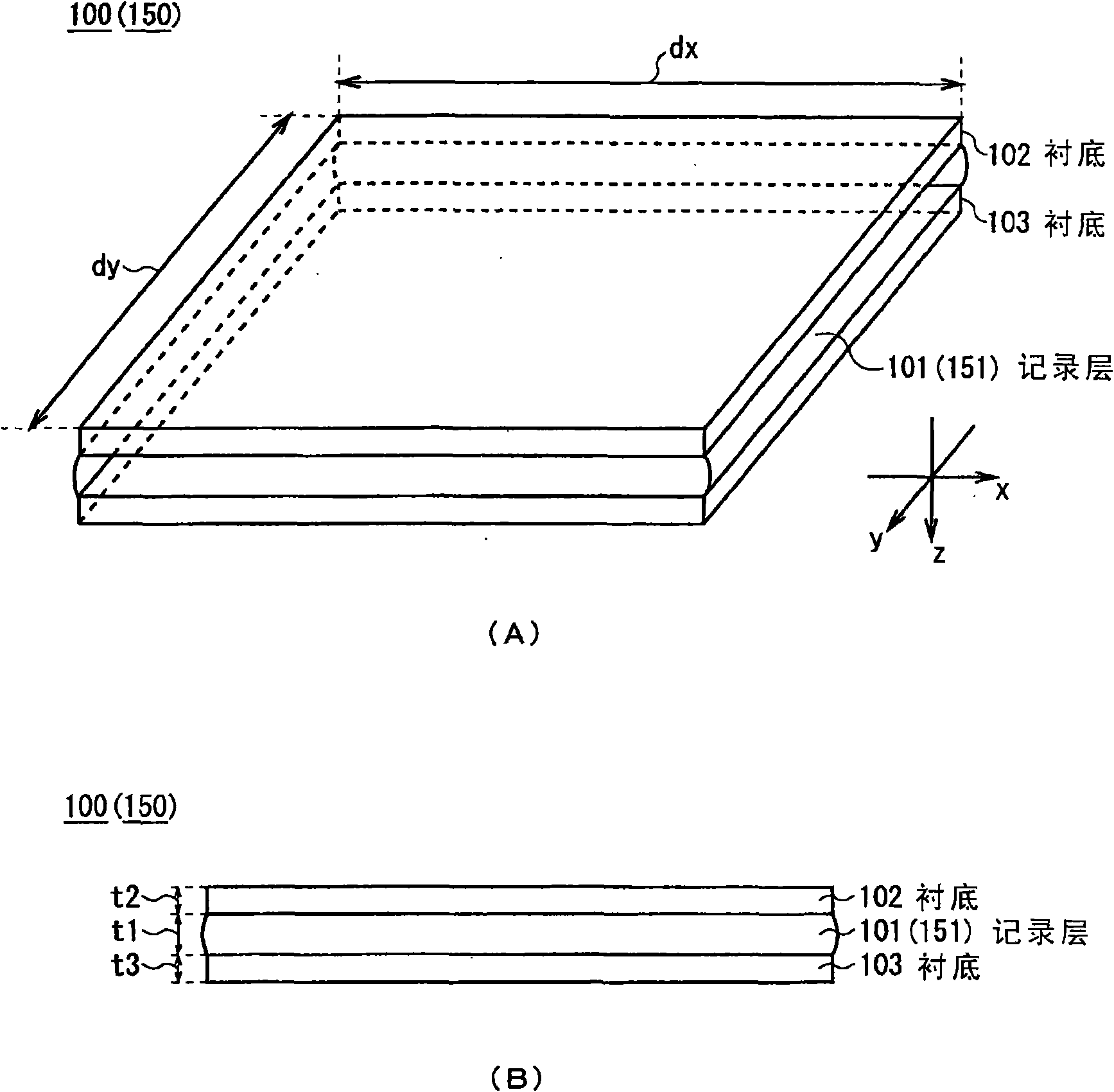
[0040] Such as figure 2 As shown in (A) and 2(B), a recording layer 101 is provided between substrates 102 and 103, thereby allowing the optical information recording medium 100 as a whole to function as a medium for recording information.

[0041] The substrates 102 and 103 are formed of glass substrates, and allow light to be transmitted through at a high rate. In addition, the substrates 102 and 103 are formed into a square or a rectangle in which the length dx along the X direction and the length dy along the Y direction are set to about 50 mm, and the thicknesses t2 and t3 are set to about 0.6 to 1.1 mm. mm.

[0042] The outer surfaces of the substrates 102 and 103 (surfaces not in contact with the recording layer 101) are subjected to anti-reflection coating (AR) treatment to form, for example, a multilayer inorganic film that is not reflective to light beams having wavelengths of 405 nm and 780 nm (e.g.,...

no. 2 approach

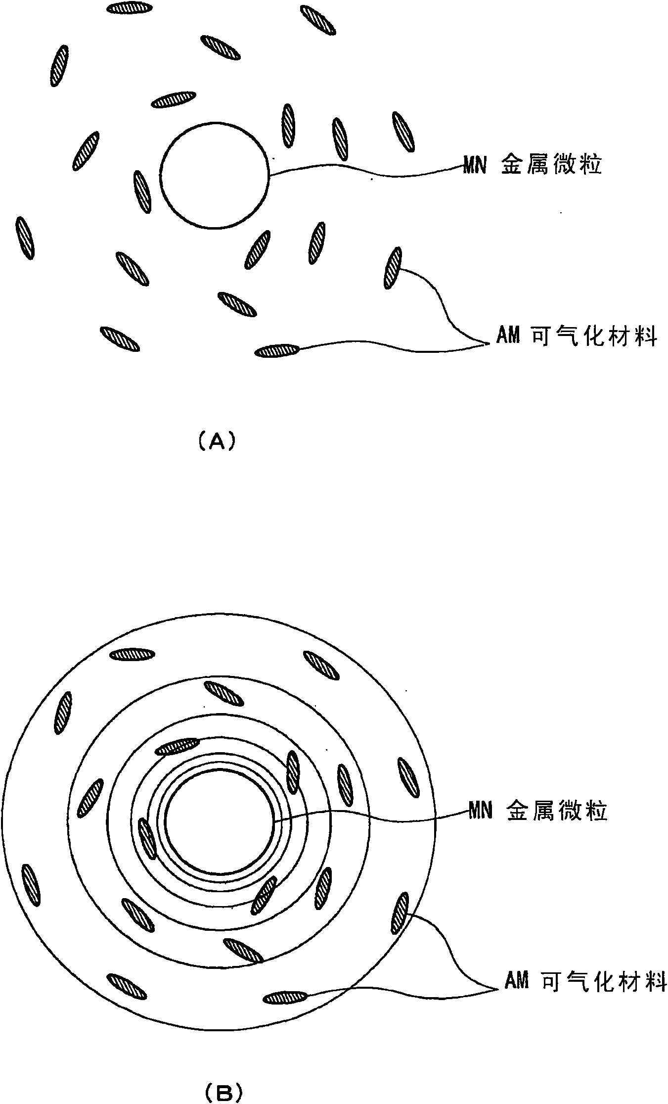
[0114] Figure 9 to Figure 10 A second embodiment is shown, where with Figure 1 to Figure 8 Corresponding parts of the first embodiment shown are denoted by the same reference numerals. The second embodiment differs from the first embodiment in that the gasifiable material AM is simply dispersed in the recording layer 151 and placed near the metal particles MN.

[0115] 3.1. Structure of optical information recording medium

[0116] Such as figure 2 As shown, similarly to the first embodiment, the structure of the optical information recording medium 150 in this embodiment is that the recording layer 151 is provided between the substrates 102 and 103 .

[0117] In the recording layer 151, the gasifiable material AM and metal fine particles MN are dispersed in a binder resin as a main component. For the binder resin and metal fine particles MN, those mentioned in the first embodiment can be used.

[0118] Metal fine particles MN are dispersed in a binder resin in a state...


PUM

PropertyMeasurementUnit
wavelengthaaaaaaaaaa

Abstract

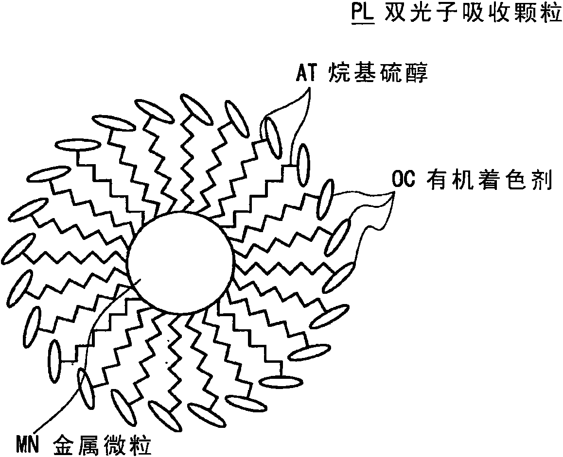
Disclosed is an optical information recording medium that can improve recording rate. Recording marks (RMs) of cavities are formed by gasifying a two photon absorbing material by a two photon absorption reaction which is one embodiment of a photoreaction upon exposure to recording light beams (L1) as a recording light collected in recording information. A recording layer (101) reproduces the information based on returned light beams (L3) that are obtained by modulating reading light beams (L2), which have been applied as predetermined reading light in reproducing the information, depending upon the presence or absence of the recording mark (RM). The recording layer (101) is formed of a material comprising two photon absorbing particles of metallic fine particles (MN), to which a two photonabsorbing material has been coordinated, dispersed in a binder resin for constituting the recording layer (101), whereby the two photon absorbing material having two photon absorbing properties as amaterial to be gasified is disposed around the metallic fine particles (MN) dispersed in the binder resin.

Description

technical field [0001] The present invention relates to an optical information recording method, an optical information recording medium, an optical information reproducing device, an optical information reproducing method, and an optical information recording and reproducing device applicable to, for example, an optical information recording medium that records information with a light beam and reproduces information with a light beam. Background technique [0002] Hitherto, disc-shaped optical information recording media have been widely used as optical information recording media, and compact discs (CDs), digital versatile discs (DVDs), Blu-ray Discs (registered trademark, hereinafter referred to as BDs) and the like are generally used. [0003] On the other hand, in an optical information recording / reproducing apparatus using the above-mentioned optical information recording medium, various types of information such as music content, picture content, or various types of d...

Claims


Application Information

Patent Timeline
Patent Type & Authority Applications(China)
IPC IPC(8): G11B7/242G11B7/0045G11B7/244
CPCB82Y10/00G11B7/251G11B7/2531G11B7/244G11B7/00452G11B7/241B82Y20/00G11B7/246G11B7/0045
Inventor 岩村贵小山田光明上田大辅
Owner SONY GRP CORP
Learn More