Fuel pump

A technology of fuel pump and fuel oil, which is applied in the direction of pumps, pump components, pump devices, etc., can solve the problem of pollutants entering, and achieve the effect of compact design, high efficiency, and avoiding the accumulation of pollutants

Inactive Publication Date: 2010-03-24
CONTINENTAL AUTOMOTIVE GMBH
View PDF0 Cites 0 Cited by
  • Summary
  • Abstract
  • Description
  • Claims
  • Application Information

AI Technical Summary

Problems solved by technology

At the same time, a pressure gradient is created between the two flanges of the blade chamber, which likewise causes contamination to enter the gap between the impeller and housing parts

Method used


Image

  • Fuel pump
  • Fuel pump

Examples


Embodiment Construction

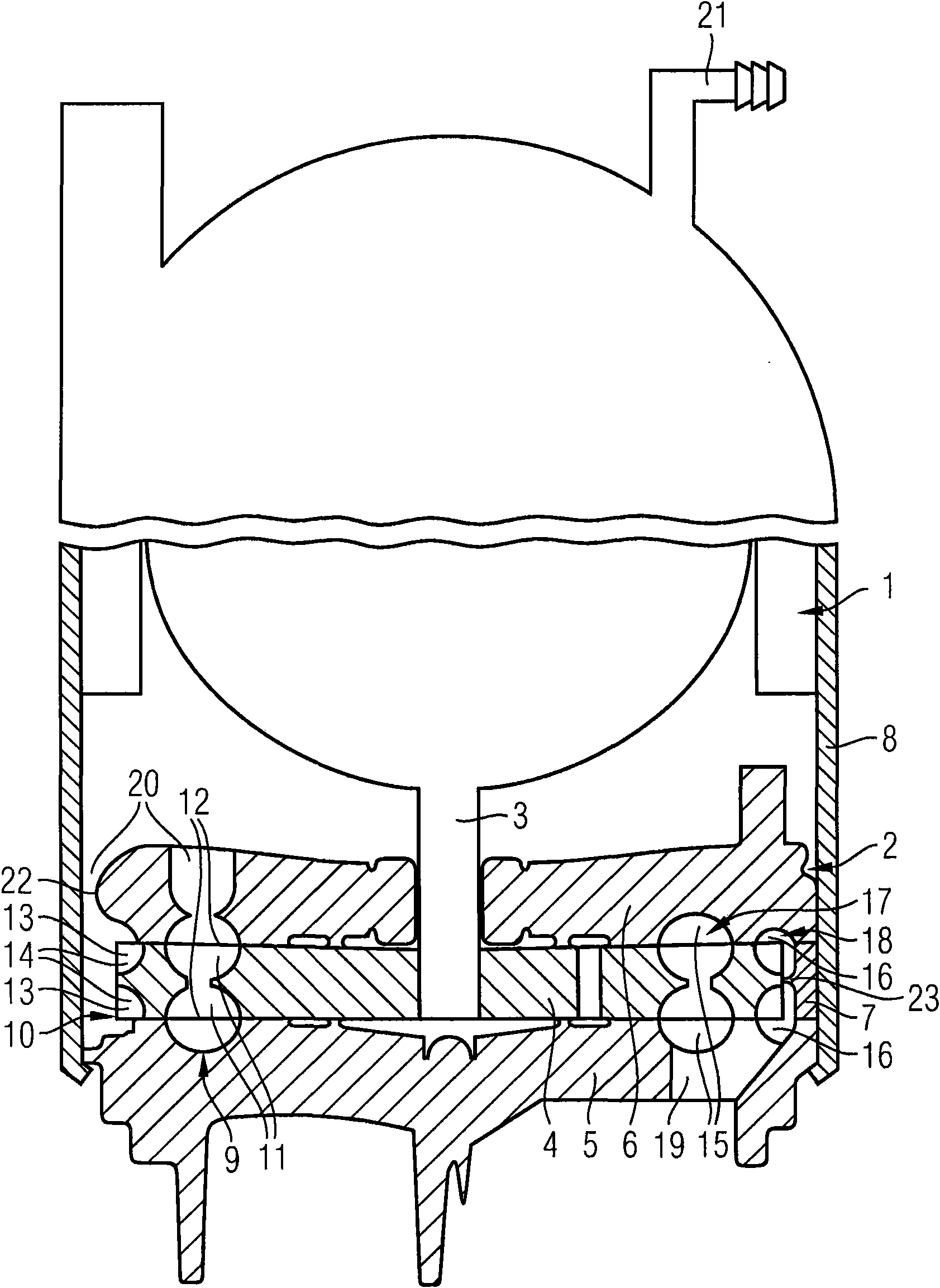
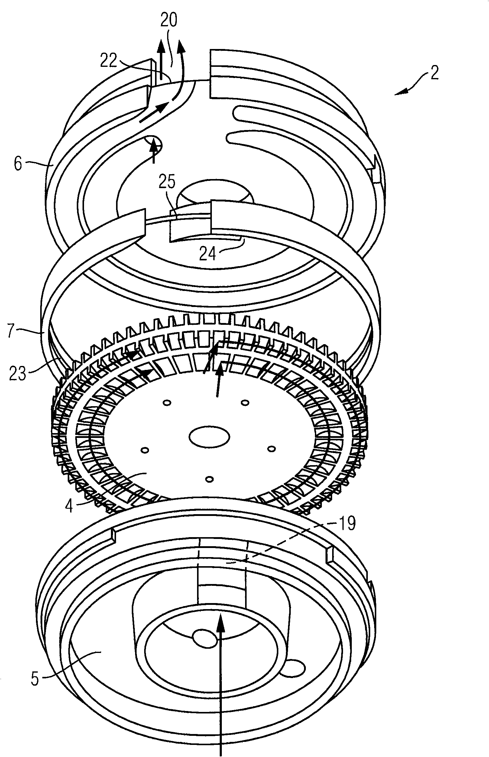
[0019] figure 1 A fuel pump is shown with a pump stage 2 driven by an electric motor 1 . The pump stage 2 has an impeller 4 which is arranged in a rotationally fixed manner on the shaft 3 of the electric machine 1 . The impeller 4 is arranged rotatably between two housing parts 5 , 6 arranged facing one another. The housing parts 5 , 6 are kept spaced apart from each other by a distance ring 7 . The casing 8 of the fuel pump pretensions the housing parts 5 , 6 relative to the spacer ring 7 . The pump stage 2 has a side channel stage 9 and a peripheral stage 10 . The side channel stage 9 has two guide vanes 12 arranged facing one another and delimiting the collar of a vane chamber arranged remote from the radially outer edge in the impeller 4 . The peripheral stage 10 has two guide vanes 14 delimiting a flange of a vane chamber 13 arranged in the radially outer edge of the impeller 4 . The vane chambers 11 , 13 each form a delivery chamber 17 , 18 together with graduated a...


PUM


Abstract

The invention relates to a fuel pump for delivering fuel in a motor vehicle, having a side channel stage (9). Said fuel pump further comprises a peripheral stage (10). Said peripheral stage (10) produces the same pressure at lower volume flow across the periphery of the rotor (4) as compared to a side channel stage (8). For this purpose, the cross-sections of the delivery compartments (18) of theperipheral stage (10) are smaller than the cross-sections of the delivery compartments (17) of the side channel stage (9). The fuel pump therefore has a higher efficiency and is less susceptible to soiling.

Description

technical field [0001] The invention relates to a fuel pump for delivering fuel in a motor vehicle, having: an impeller rotatable between an inlet-side housing part and an outlet-side housing part; a channel stage, wherein the side channel stage has a conveying chamber extending from the inlet to the outlet, the conveying chamber has guide vanes of a flange arranged in the impeller delimiting the vane chamber, and the mutually facing vanes of the side channel stage The chambers are interconnected. Background technique [0002] Such fuel pumps are frequently used in modern motor vehicles and are known from practice. The side channel stage of the known fuel pump is axially open and conveys fuel from the fuel tank to the internal combustion engine of the motor vehicle. Side channel stages with blade chambers remote from the outer edge of the impeller have a high efficiency, but tend to allow contamination particles to enter the gap between the impeller and the housing part, e...

Claims


Application Information

Patent Timeline
Patent Type & Authority Applications(China)
IPC IPC(8): F04D5/00F04D13/12F04D29/18
CPCF04D5/005F04D13/12F04D29/188F04D29/007F04D29/406F05D2210/11F05D2260/60Y10S415/00Y10S417/00
Inventor 贝恩德·耶格约翰内斯·戴希曼马蒂亚斯·菲舍尔
Owner CONTINENTAL AUTOMOTIVE GMBH
Why Eureka
Try Eureka