Dispenser-cap device for bottles

A bottle cap and sealing device technology, applied in the field of bottle cap devices for bottles, can solve problems such as incomplete solutions

Inactive Publication Date: 2010-03-24
捷飞特股份公司
View PDF0 Cites 3 Cited by
  • Summary
  • Abstract
  • Description
  • Claims
  • Application Information

AI Technical Summary

Problems solved by technology

[0005] So these solution...

Method used


Image

  • Dispenser-cap device for bottles
  • Dispenser-cap device for bottles
  • Dispenser-cap device for bottles

Examples


Embodiment Construction

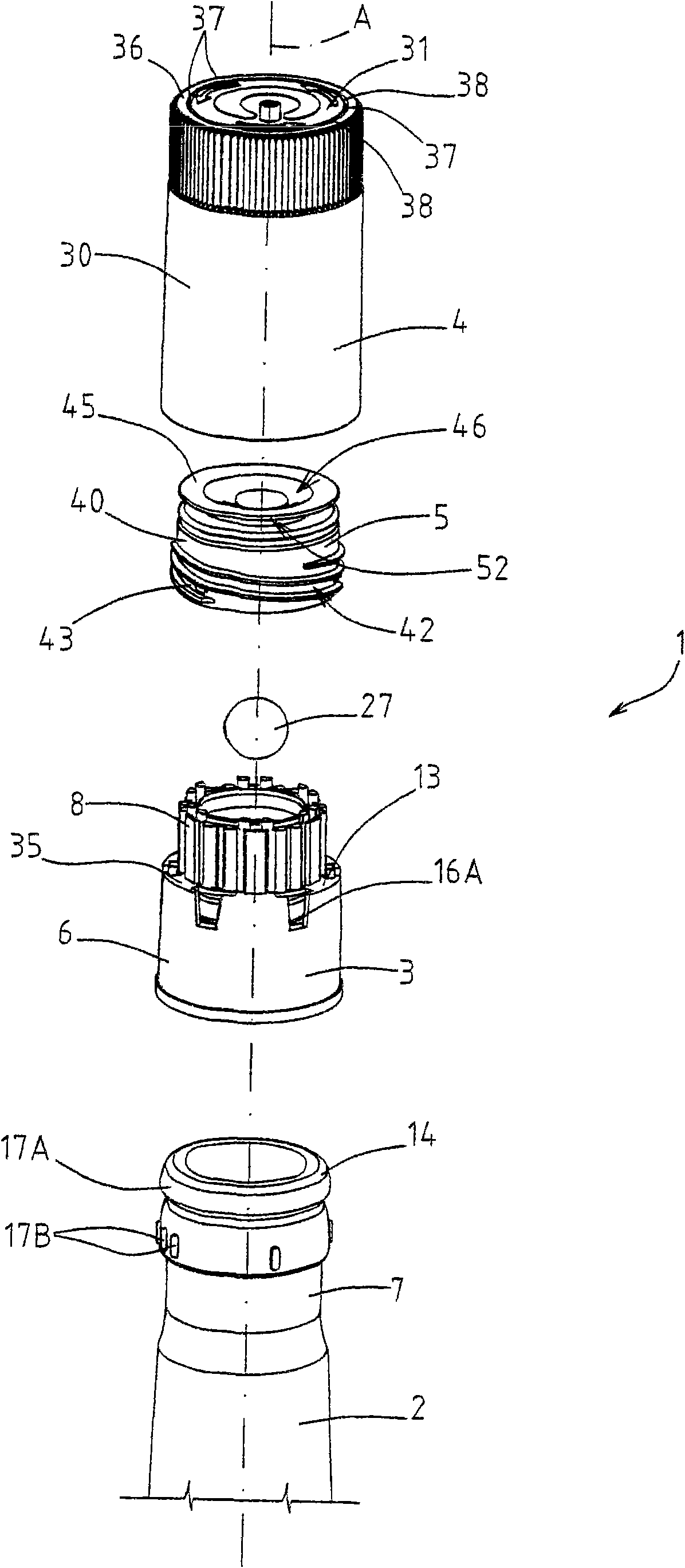
[0016] exist figure 1 , reference numeral 1 generally designates a bottle cap device for a bottle 2, such as a wine / alcohol bottle or other alcoholic beverage bottle.

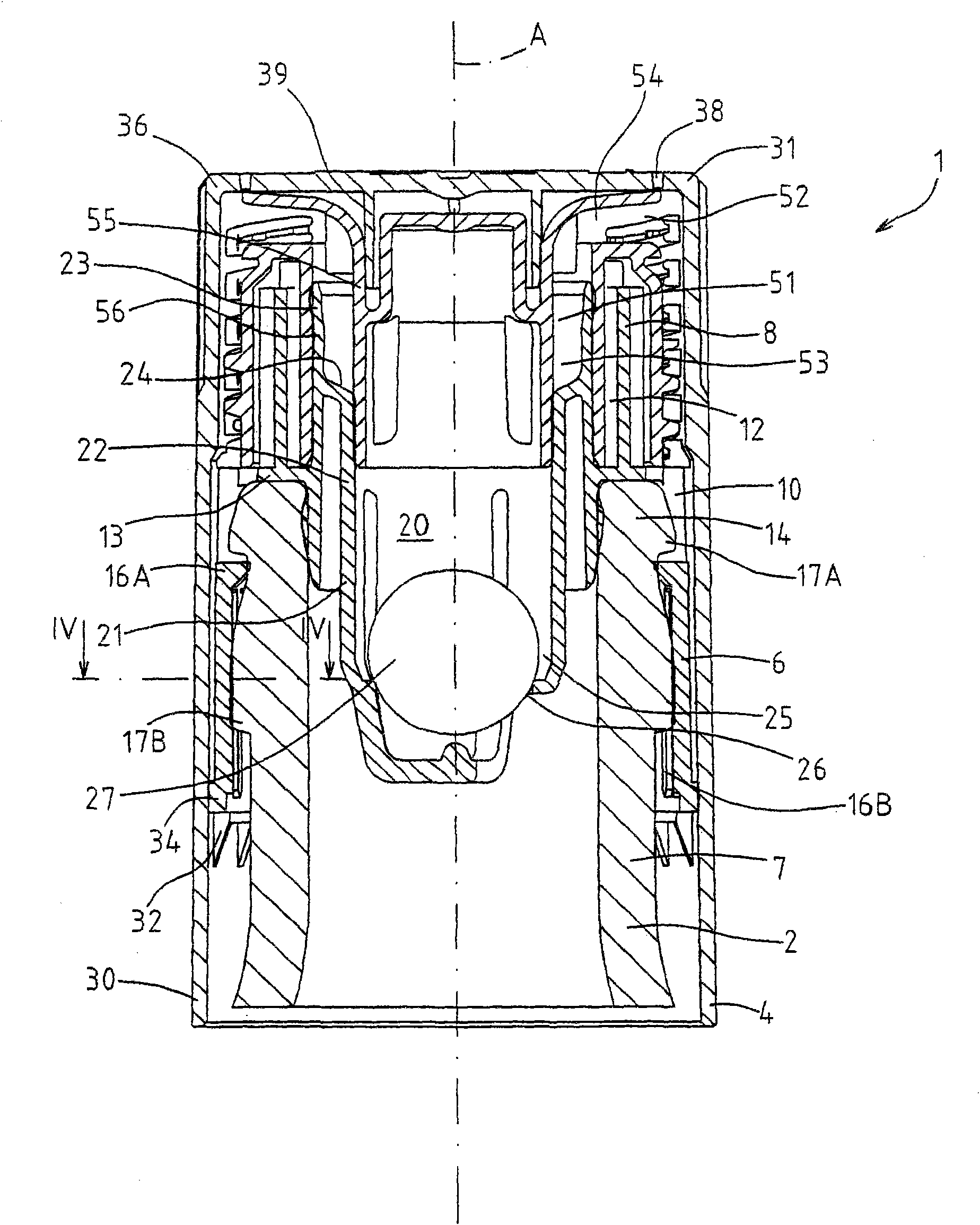
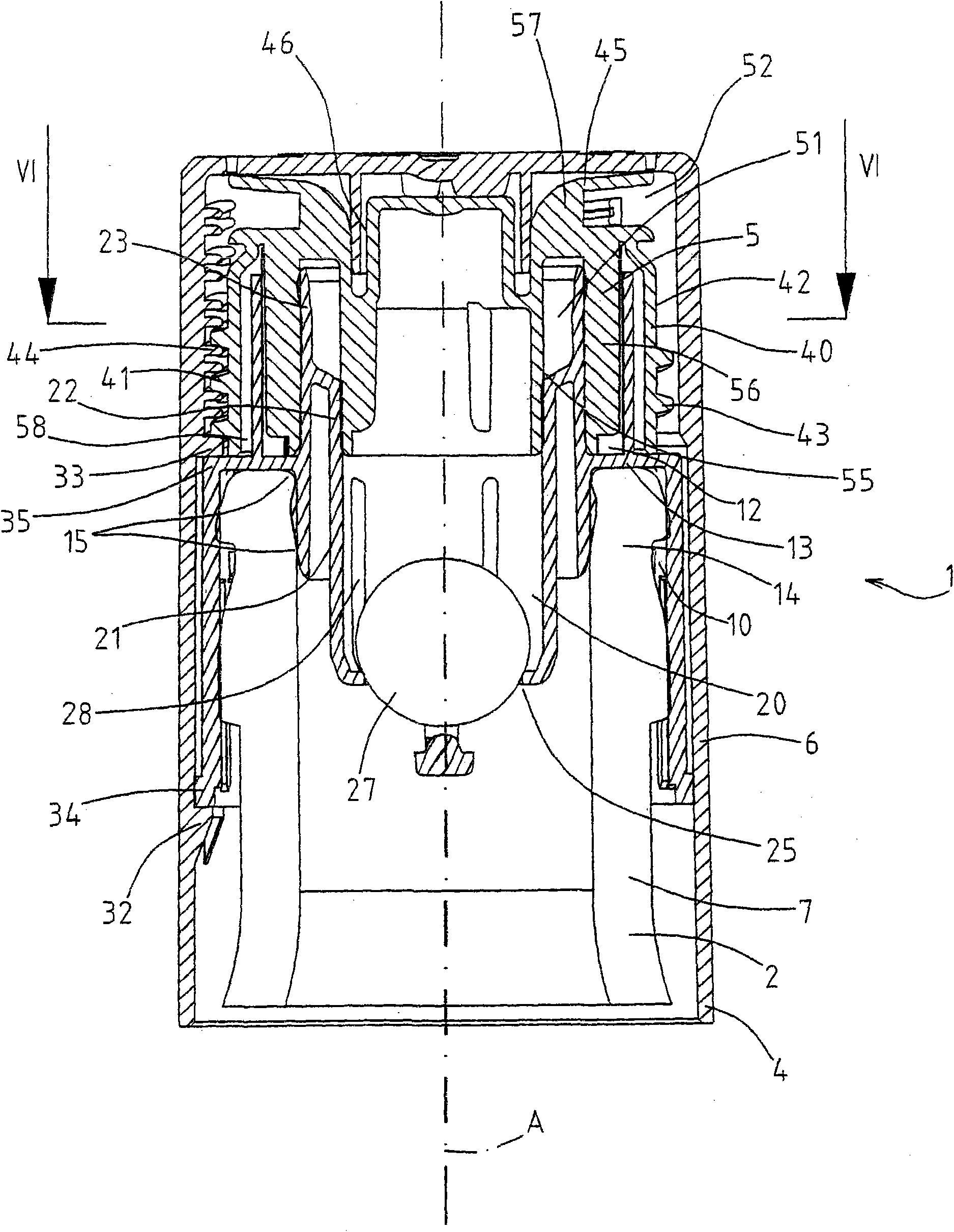
[0017] The device 1 extends substantially along the axis A and comprises a base body 3, a handle element 4 and a spout element 5, which are preferably formed from respective single pieces of plastic material.

[0018] see also Figure 2-4 , the base 3 includes a connecting portion 6 and a guiding portion 8, the connecting portion 6 is used to be fastened to the neck 7 of the bottle 2, and the guiding portion 8 protrudes axially from the connecting portion 6 to cooperate with the spout element 5; the connecting portion 6 and the guiding portion The portion 8 is provided with respective axially opposed generally annular seats 10, 12 positioned about the axis A; the seats 10, 12 are defined by respective pairs of coaxial and generally cylindrical side walls which They are connected to each other via an annular f...


PUM


Abstract

A dispenser-cap device (1) for a bottle extends substantially along an axis(A) and is formed by: an essentially tubular base body (3), connectable in a fluid-tight manner to a neck (7) of the bottle(2) and having an inner chamber (20); a handle element(4), rotatably coupled to the base body and axially connected to the base body; and a spout element (5) having a channel (51)communicating with thechamber; the spout element (5) is telescopically coupled to the handle element (4) by respective threaded portions (43, 44) and being slidable with respect to the base body (3) along the axis (A) dueto rotation of the handle element (4) with respect to the base body (3) for selectively opening/closing a passage (63) between the channel (51) and the chamber (20).

Description

technical field [0001] The present invention relates to a capping device for bottles, in particular for bottles of wine, alcohol or other precious beverages. Background technique [0002] Wine bottles are generally known to be provided with a screw cap which allows frequent opening / closing of the bottle, which in most cases is screwed directly onto an external thread formed on the neck of the bottle. [0003] In order to prevent the bottle from being refilled with a different liquid than the original (and thus prevent low-quality products from being illegally sold in the original bottle), it is known to use a spout element, which is usually inserted in the neck of the bottle and has a double function: both to regulate the filling Liquid volume, in turn prevents possible refilling of the bottle, or at least makes such refilling difficult. [0004] In known solutions, the spout element is usually forced into the neck of the bottle and can be removed very easily (and in some c...

Claims


Application Information

Patent Timeline
IPC IPC(8): B65D47/24B65D49/04
CPCB65D47/244B65D2101/003B65D49/04B65D2401/20
Inventor 毛里齐奥·索尔泽
Owner 捷飞特股份公司
Why Eureka
Try Eureka