
Transformer used for reducing electromagnetic interference influence and applicable power switching circuit thereof

A power conversion circuit, electromagnetic interference technology, applied in the field of transformers, can solve problems such as affecting the electromagnetic coupling rate and reducing the operating efficiency of transformers

Inactive Publication Date: 2010-03-17
DELTA ELECTRONICS INC
View PDF0 Cites 7 Cited by
  • Summary
  • Abstract
  • Description
  • Claims
  • Application Information

AI Technical Summary

Problems solved by technology

[0005] The main purpose of the present invention is to provide a transformer for reducing the influence of electromagnetic interference and its applicable power conversion circuit, to solve the problem that the primary winding is repeatedly switched due to the switching element when the known transformer is applied to the power conversion circuit and is electrically connected to the switching element The generated electromagnetic interference will affect the electromagnetic coupling rate between it and the secondary winding, which will reduce the operating efficiency of the transformer

Method used


Image

  • Transformer used for reducing electromagnetic interference influence and applicable power switching circuit thereof
  • Transformer used for reducing electromagnetic interference influence and applicable power switching circuit thereof
  • Transformer used for reducing electromagnetic interference influence and applicable power switching circuit thereof

Examples


Embodiment Construction

[0043] Some typical embodiments embodying the features and advantages of the present invention will be described in detail in the description in the following paragraphs. It should be understood that the present invention can have various changes in different embodiments, all of which do not depart from the scope of the present invention, and the description and illustrations therein are used as illustrations in nature, not for limit the invention.

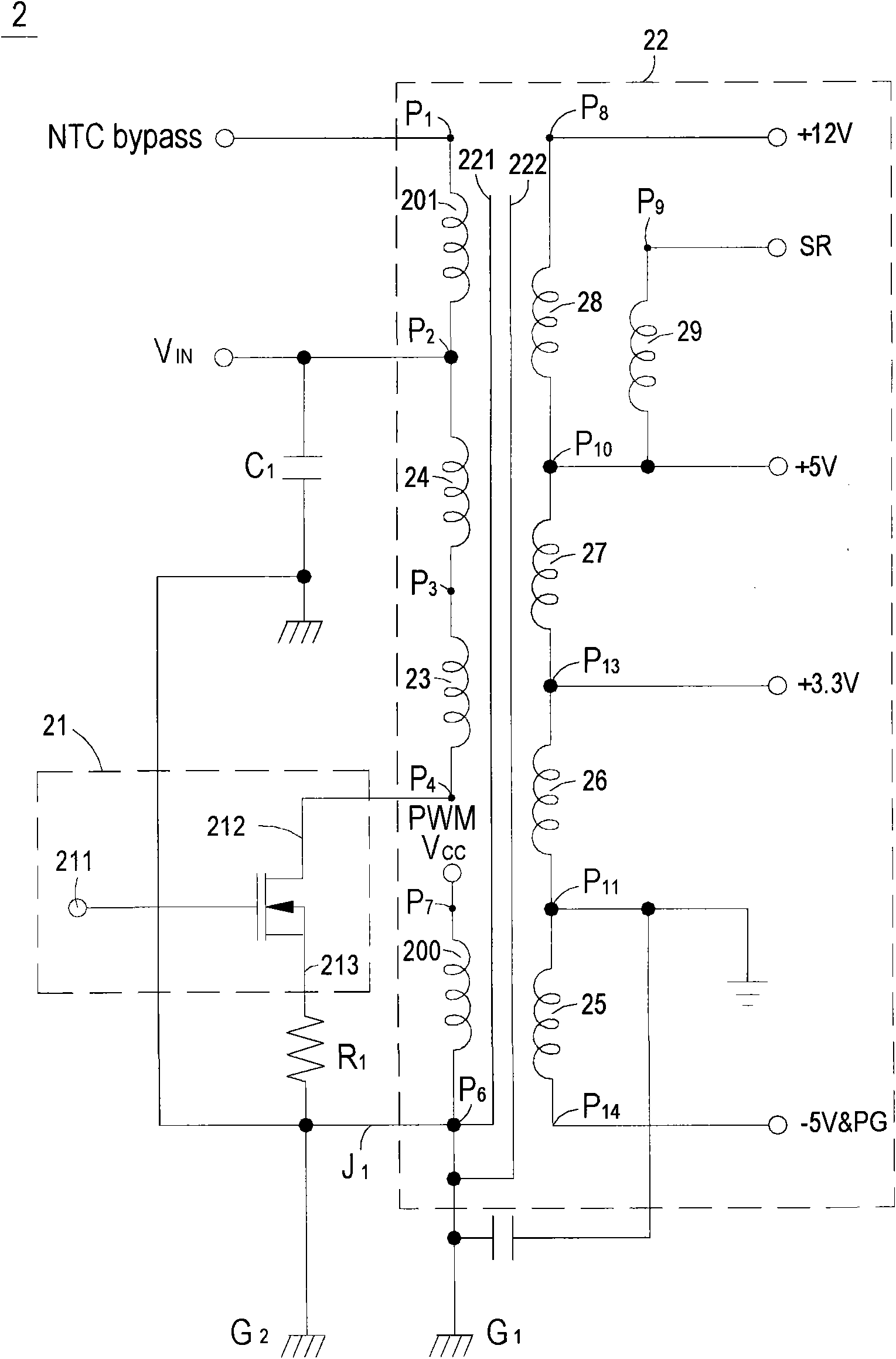
[0044] see figure 2 , which is a circuit structure diagram of a power conversion circuit using a transformer capable of reducing the influence of electromagnetic interference according to a preferred embodiment of the present invention. Such as figure 2 As shown, the power conversion circuit 2 of this embodiment mainly includes a power input terminal VIN, a switch element 21 and a transformer 22 . The transformer 22 is electrically connected to the power input terminal VIN and the switch element 21 respectively, and includes ...


PUM


Abstract

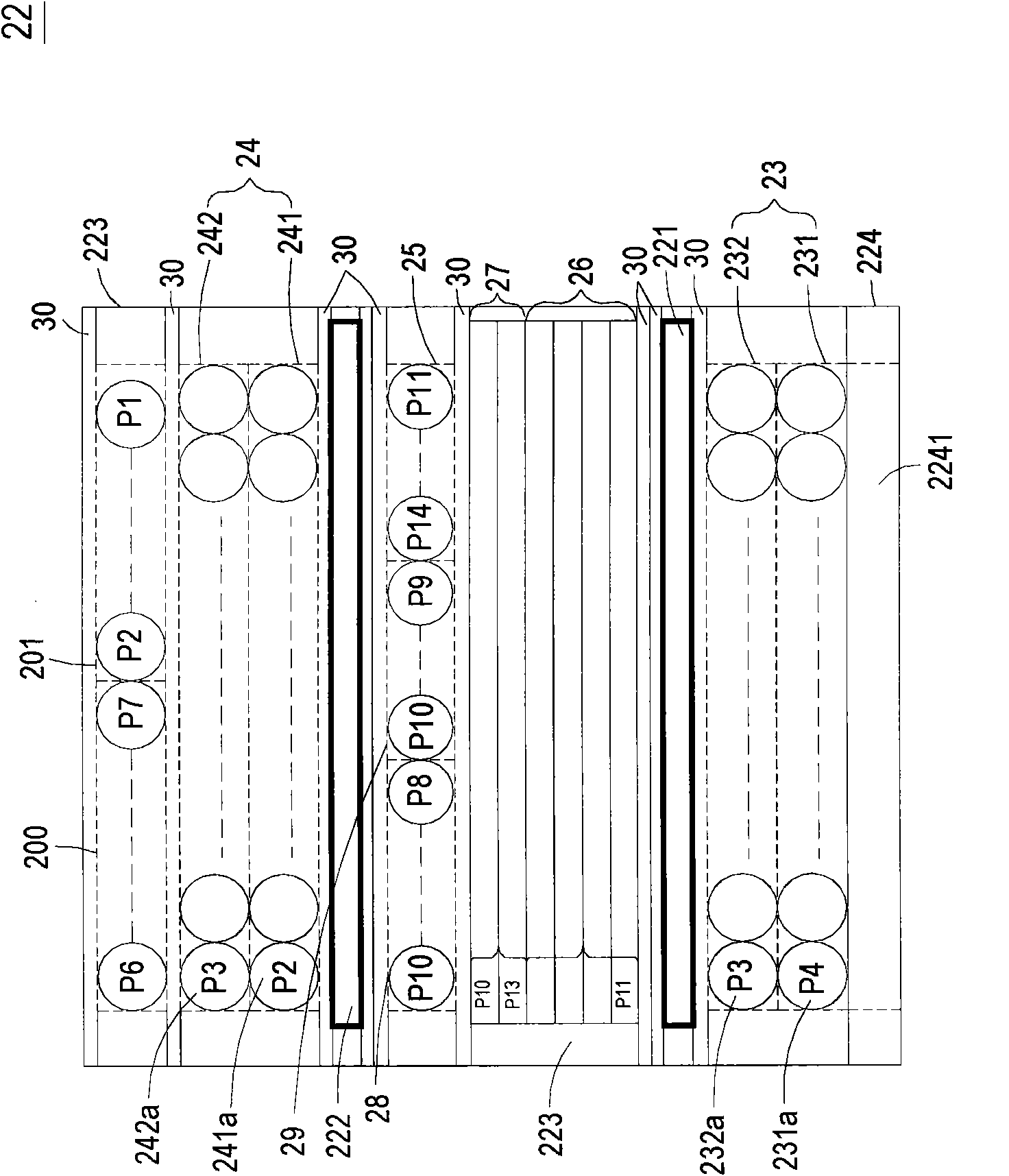
The invention relates to a transformer used for reducing electromagnetic interference influence and an applicable power switching circuit thereof. The transformer at least comprises a winding base, amagnetic core group partially penetrating the winding base, a first primary winding wound on the winding base and composed of a first winding part and a second winding part, a secondary winding woundon the first primary winding, and a first screening element arranged between the first primary winding and the secondary winding to be used for preventing the electromagnetic interference of the firstprimary winding from being conducted to the secondary winding, wherein the electromagnetic interference of the first winding part is larger than that of the second winding part; the first winding part of the first primary winding is arranged near the magnetic core group so as to screen the electromagnetic interference of the first winding part by the magnetic core group; the second winding part is wound on the first winding part and is adjacent to the secondary winding so as to increase the electromagnetic coupling efficiency of the first primary winding and the secondary winding. The invention can reduce the influence the electromagnetic interference to the transformer, thereby enabling the transformer to reduce leakage inductance, and therefore, the converting efficiency is improved.

Description

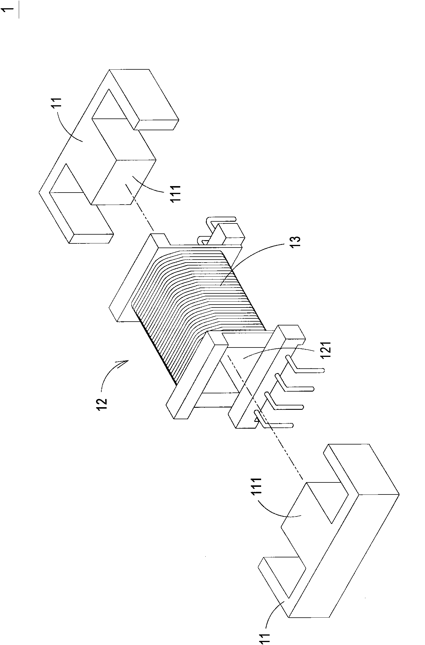
technical field [0001] The invention relates to a transformer, in particular to a transformer for reducing the influence of electromagnetic interference and a suitable power conversion circuit thereof. Background technique [0002] Transformers are electronic components often used in various electrical equipment. see figure 1 , which is a structural schematic diagram of a known transformer. Such as figure 1 As shown, the transformer 1 mainly includes a magnetic core assembly 11 , a bobbin base 12 , a primary winding 13 and a secondary winding (not shown). Wherein, the primary winding 13 and the secondary winding are sandwich wound in the winding area of ​​the winding base 12, that is, the primary winding 13 is divided into two parts and the secondary winding is covered therein. , and two adjacent positions of the primary winding 13 and the secondary winding are insulated and separated from each other by tape. The magnetic core group 11 is usually an EE type magnetic cor...

Claims


Application Information

Patent Timeline
IPC IPC(8): H01F27/28H01F27/36H01F41/06H02M5/10
Inventor 欧阳志弘许志勋林瑞玲
Owner DELTA ELECTRONICS INC
Learn More