
Leg device

A telescopic foot and foot support technology, applied in the direction of supporting machines, machines/brackets, circuits, etc., can solve the problems of small telescopic ratio of telescopic legs, inability to ensure height, and insufficient compactness, and achieve improved foot telescopic ratios, The effect of improving the expansion ratio of the foot

Inactive Publication Date: 2010-03-10
VELBON
View PDF1 Cites 0 Cited by
  • Summary
  • Abstract
  • Description
  • Claims
  • Application Information

AI Technical Summary

Problems solved by technology

[0005] However, like the above-mentioned existing leg device, when the telescopic leg body is contracted, the upper end of the second tubular member abuts against the fulcrum and is located below the fulcrum. In such a structure, the telescopic leg body The leg stretch ratio is small, so for example, if the compactness when not in use is pursued when carrying, etc., the required height cannot be ensured when in use. Conversely, if the height when used is pursued, the compactness when not in use is insufficient. possible

Method used


Image

  • Leg device
  • Leg device
  • Leg device

Examples


Embodiment Construction

[0022] One embodiment of the stand device of the present invention will be described with reference to the drawings.

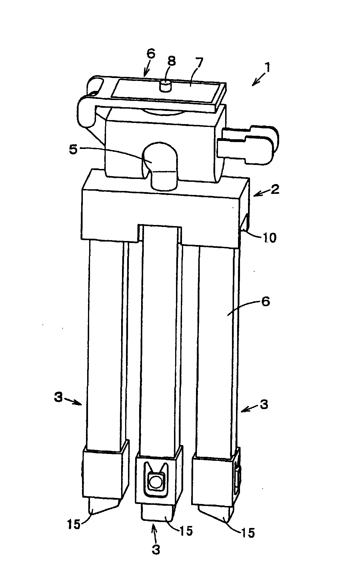
[0023] exist figure 1 Among them, reference numeral 1 is a leg device, and this leg device 1 is a tripod with a head for supporting a supported object (not shown) such as a camera or a video camera.

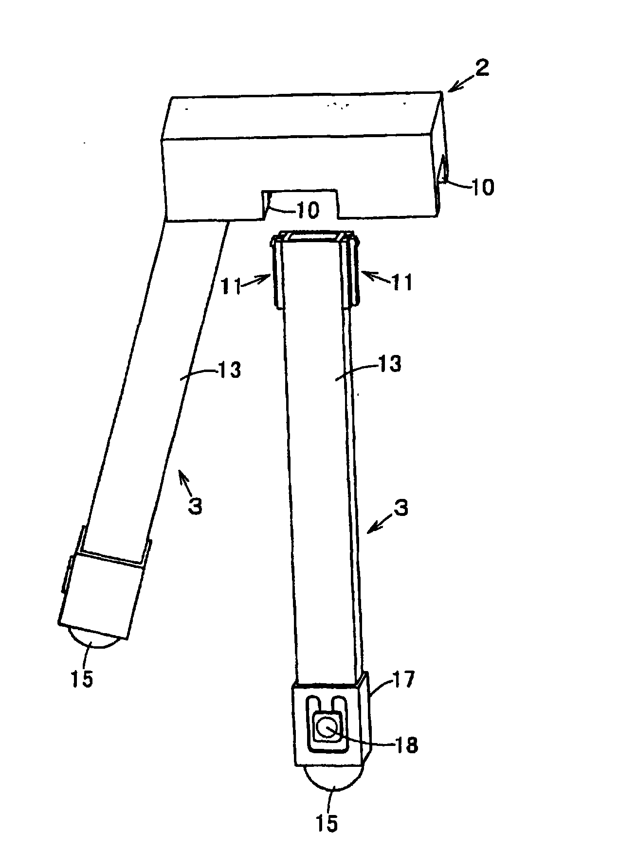
[0024] The stand device 1 includes a base body 2 having an approximately rectangular parallelepiped shape. On the lower surface side of the base body 2, upper end portions of a plurality of, for example, three elongated telescopic legs 3 that can expand and contract in the longitudinal direction are rotatably attached. A substantially spherical pan-tilt holder 5 protrudes from the upper surface of the base body 2 , and a pan-tilt 6 is attached to the pan-tilt holder 5 , and the pan-tilt 6 can rotate in all directions. The platform 6 has a support plate portion 7 for supporting an object to be supported, and screws 8 screwed into threaded holes on the lower surf...


PUM


Abstract

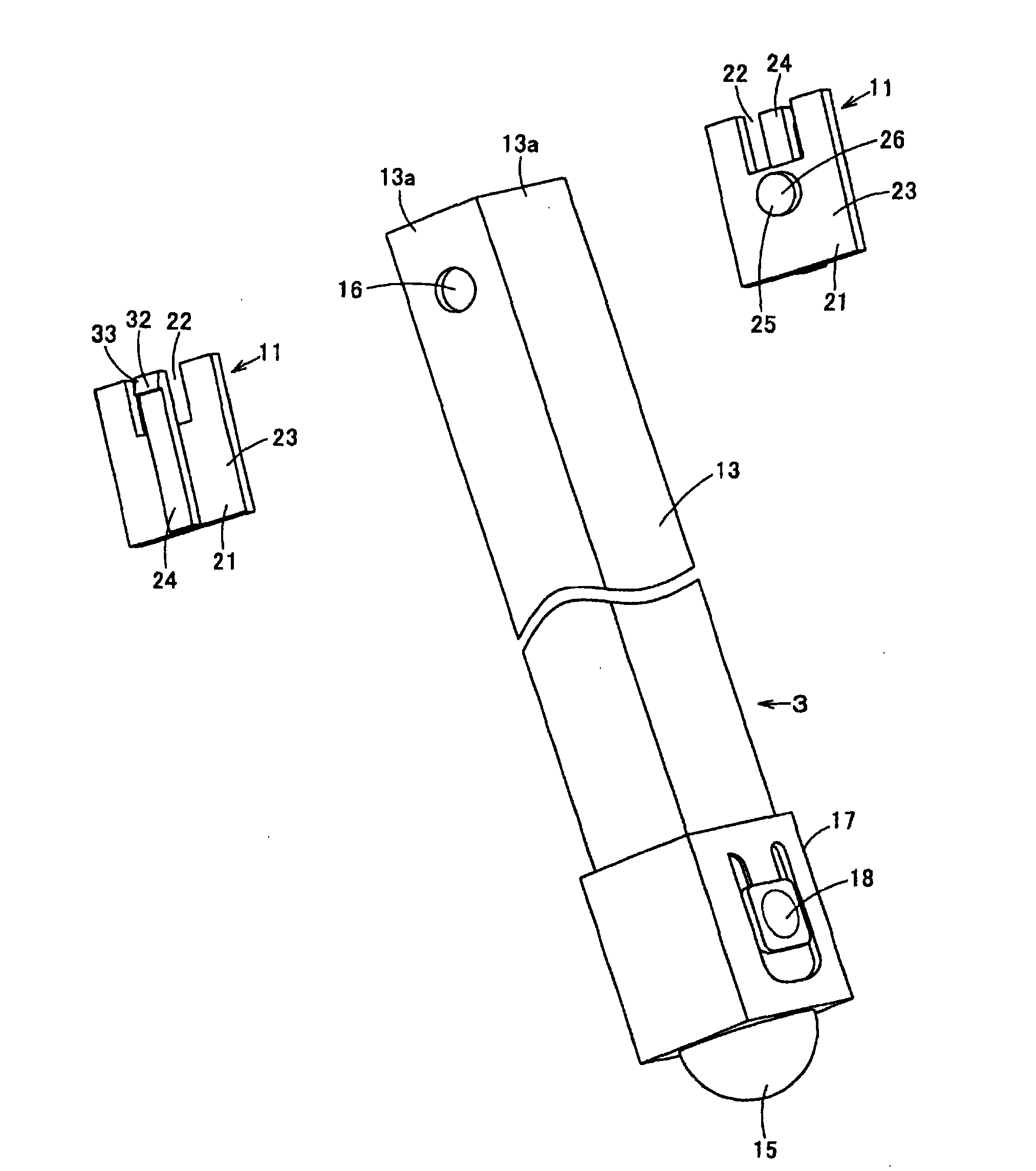
A leg device that ensures a necessary height at use and can be satisfactorily compact at nonuse. The leg device (1) includes a base body (2), a telescopic leg body (3) being turnable against the basebody (2) and a leg support body (11) turnably supporting the telescopic leg body (3). The telescopic leg body (3) has a first tubular member (13) provided in the vicinity of its superior edge with a fitting hole part (16). A second tubular member (14) provided with a projection from the inferior edge of the first tubular member (13) whose length is adjustable is inserted in the first tubular member (13). The leg support body (11) has a spindle part (25) turnably fitted in the fitting hole part (16). When the telescopic leg body (3) is in the state of being shortened, the superior edge of the second tubular member (14) is located above the spindle part (25).

Description

technical field [0001] The present invention relates to a foot device that can ensure a desired height when in use and is sufficiently compact when not in use. Background technique [0002] Conventionally, a leg device such as a tripod described in FIGS. 7 and 8 of Patent Document 1 below is known. [0003] This conventional leg device includes a base body, a telescopic leg body rotatable relative to the base body, and a support shaft connecting the base body and the telescopic leg body. The telescopic leg body has: a first tubular member having a through-hole through which a fulcrum is inserted; and a second tubular member movably inserted into the first tubular member, the second tubular member The movement of a tubular member can adjust the protruding length from the lower end of the first tubular member. In addition, when the telescopic legs are contracted, the upper end of the second tubular member abuts against the support shaft and is positioned below the support sh...

Claims


Application Information

Patent Timeline
Patent Type & Authority Applications(China)
IPC IPC(8): F16M11/32
CPCF16M11/14F16M11/32F16M11/16F16M2200/022Y10T403/606
Inventor 中谷幸一郎
Owner VELBON
Learn More