Large-current electric rotary connector

A rotary connector, high-current technology, applied in the direction of rotary current collectors, connections, current collectors, etc., can solve the problem of large heat generation of brushes and electric slip rings, improve transmission performance and use performance, and ensure current carrying. Ability, ease of positioning and effect of assembly

Inactive Publication Date: 2012-01-04
CHINA AVIATION OPTICAL-ELECTRICAL TECH CO LTD
View PDF0 Cites 0 Cited by
  • Summary
  • Abstract
  • Description
  • Claims
  • Application Information

AI Technical Summary

Problems solved by technology

[0003] The purpose of the present invention is to provide a high-current electric rotary connector to solve the problem of large heat generation between the brush and the electric slip ring when the existing high-current electric rotary connector is in use

Method used


Image

  • Large-current electric rotary connector
  • Large-current electric rotary connector
  • Large-current electric rotary connector

Examples


Embodiment Construction

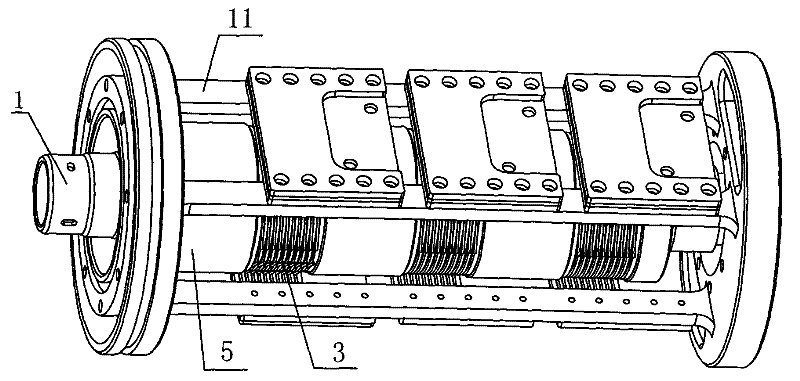
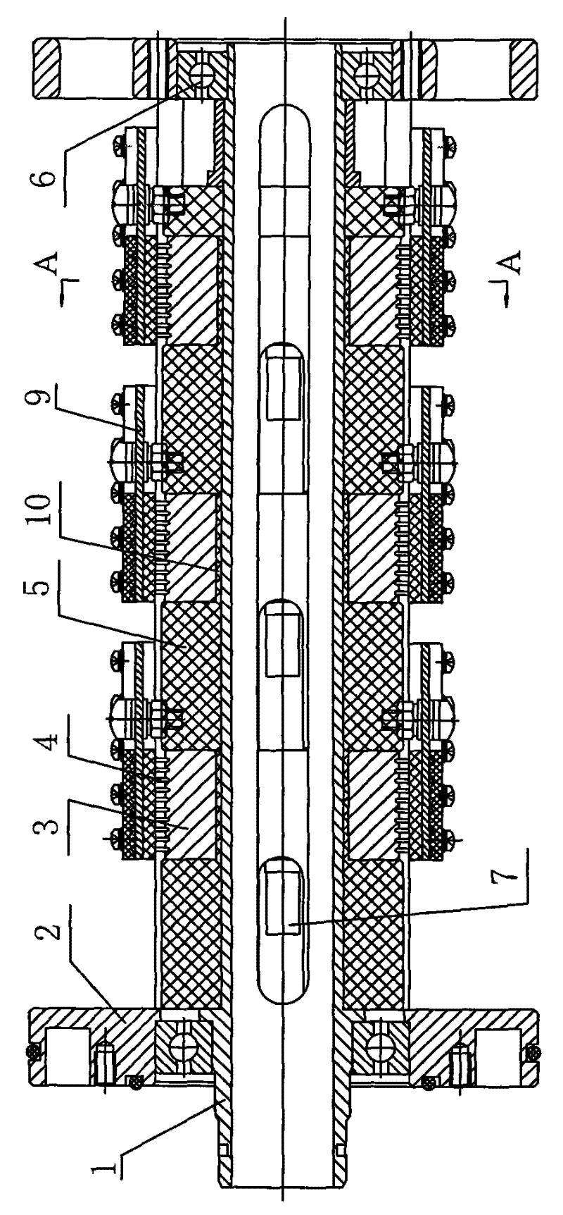
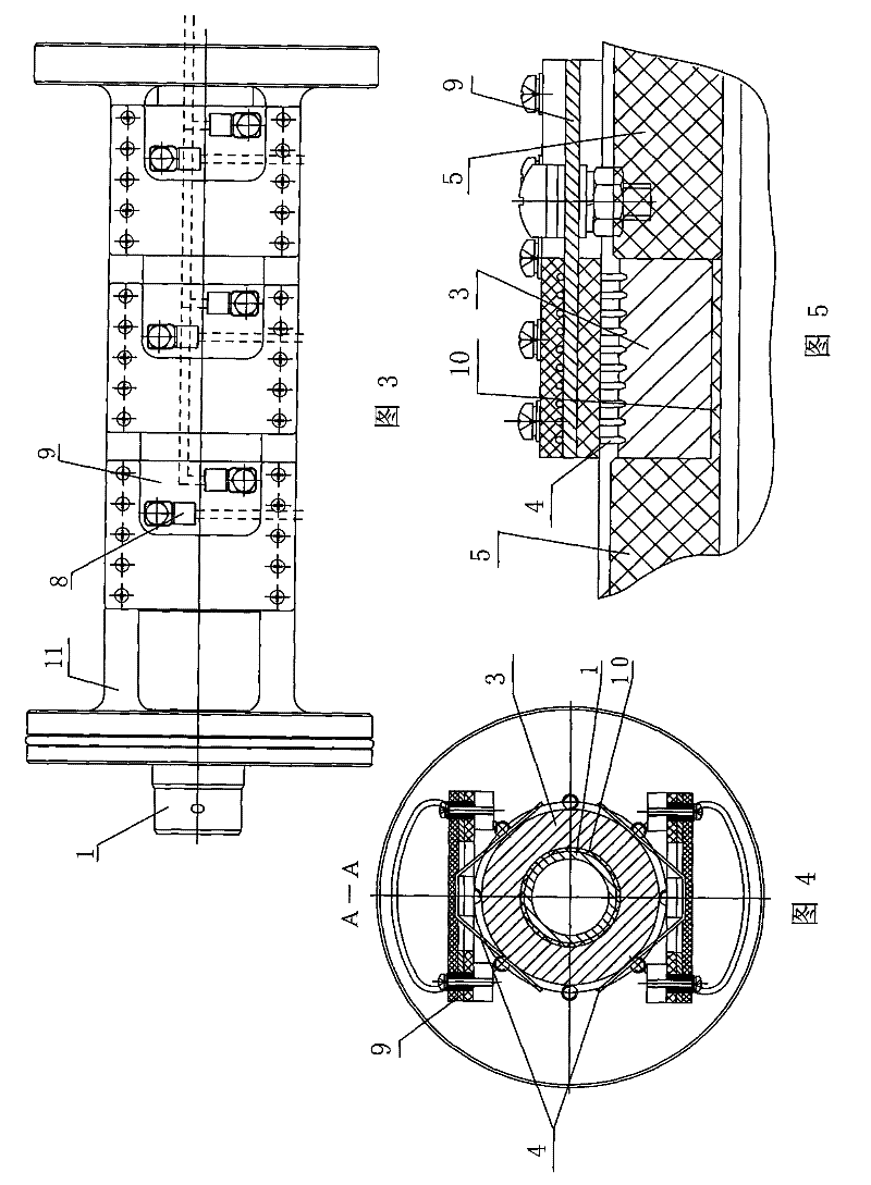
[0017] Figure 1-5 The high-current electrical rotary connector shown includes a hollow slip ring shaft 1, a first cable joint 7 is provided inside the slip ring shaft, and support frames 2 are set on both ends of the slip ring shaft, and the two support frames pass through the bridging beam 11 is connected as a whole, and a bearing support 6 is installed between the slip ring shaft 1 and the support frame 2; the part of the slip ring shaft between the two bearing supports is alternately sleeved with an insulator 5 and an electric slip ring 3, and each electric slip ring 3 An insulating sleeve 10 is provided between the inner hole of the slip ring and the shaft of the slip ring. Each insulating sleeve 10 is integrally formed with the insulator 5 located on the same side of the corresponding electric slip ring. Of course, it can also be separated. Each electric slip ring 3 The insulator 5 and the insulating sleeve 10 are insulated and matched with the slip ring shaft 1, and two...


PUM


Abstract

The invention relates to a large-current electric rotary connector, which comprises a slip-ring shaft; insulators and electric slip-rings are alternately sheathed on the slip-ring shaft; each electric slip-ring is matched with the slip-ring shaft in an insulating way; the circumferential periphery of each electric slip-ring is provided with a corresponding electric brush device respectively; the electric brush device comprises a confluence plate and an electric brush group; the electric brush group consists of electric brush monomers that are axially and intermittently arranged on the confluence plate; each electric brush monomer is conducted with the confluence plate; and the working end of each electric brush monomer is elastically pressed and contacted on the surface of the electric slip-ring corresponding to the electric brush device so as to form a rotary sliding contact matching. The connector changes the existing whole press-contact into press-contact of each electric brush monomer, thus ensuring the total contact width of the electric slip-ring; as the width of the electric brush monomer is greatly reduced, small press-contact force is needed to ensure the reliable contactbetween the electric brush monomer and the electric slip-ring, thereby greatly reducing the heat generated due to excessively large friction force and bad contact.

Description

technical field [0001] The invention relates to an electric rotary connector. Background technique [0002] The electrical rotary connector is an electrical connector that can transmit signals and power in a rotating state. During the rotation, the cables used to transmit signals and power will not be twisted and damaged. The main components of the electrical rotary connector are electrical slip rings and brushes, and the relative rotating sliding contact between the electrical slip rings and the brushes is used to complete the transmission of signals and power. The structure of the electrical rotary connector is quite different depending on the occasion it is used in and the magnitude of the current to be transmitted. There is an electrical rotary connector that transmits a large current, including a hollow slip ring shaft, a slip ring There is a cable joint inside the shaft, a support frame is set at both ends of the slip ring shaft, a bearing support is installed between...

Claims


Application Information

Patent Timeline
Patent Type & Authority Patents(China)
IPC IPC(8): H01R39/64H01R39/38
Inventor 朱晓东
Owner CHINA AVIATION OPTICAL-ELECTRICAL TECH CO LTD
Why Eureka
Try Eureka