Refrigerating tank container

A tank container and refrigeration system technology, applied in the field of containers, can solve problems such as inability to load and unload as a whole, increase risk factors, increase transportation costs and material loss, and achieve the effect of flexible loading and unloading and flexible transportation

Inactive Publication Date: 2010-03-10
NINGBO MINGXIN CHEM MACHINERY
View PDF0 Cites 3 Cited by
  • Summary
  • Abstract
  • Description
  • Claims
  • Application Information

AI Technical Summary

Problems solved by technology

If the same liquid, such as beer, is to be transported over a long distance, it must be filled by train into the brewery, then poured into the place of use after being transported to the destination, and then transported to the beer station or beer station after being filled by the car from the place of use. The user unit pours the beer into the beer storage warehouse, which cannot realize the intermodal transport of railways, highways, and waterways because it cannot be loaded and unloaded as a whole, and must go through multiple transshipments, multiple fillings and canning, which not only increases transportation costs and Material loss, and many risk factors have been added, which brings a lot of inconvenience to transportation, storage and use
Containers, as a standard transport container, have been widely used at home and abroad. Although these containers have realized the standardization and convenience of liquid material transportation, the temperature of non-hazardous liquid media such as beer needs to be maintained at low temperature during transportation. Temperature range, and the existing containers cannot meet the special requirements for the temperature in the long-distance transportation of liquid media (such as beer, etc.), so it is necessary to improve the structure of the existing containers to achieve lower temperature requirements Long-distance transportation of liquid media (such as beer, etc.)

Method used


Image

  • Refrigerating tank container
  • Refrigerating tank container

Examples


Embodiment Construction

[0020] The following are specific embodiments of the present invention and in conjunction with the accompanying drawings, the technical solutions of the present invention are further described, but the present invention is not limited to these embodiments.

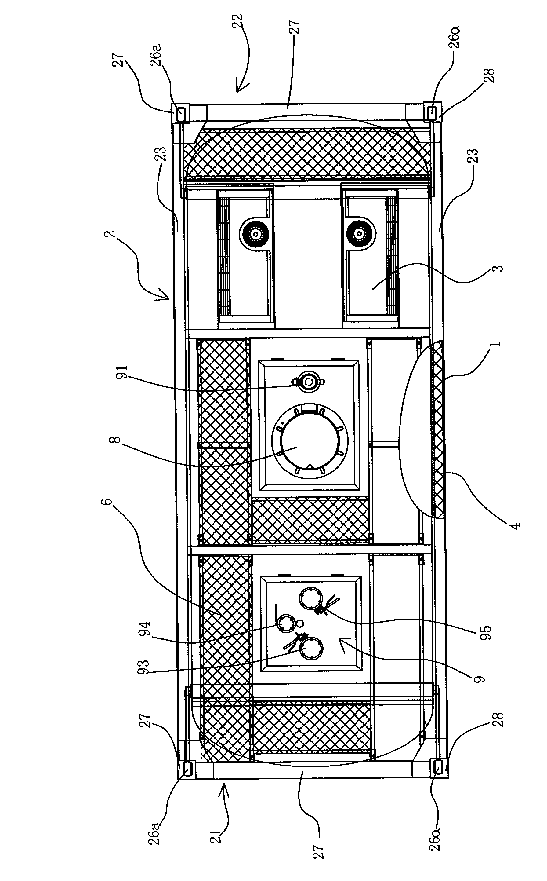
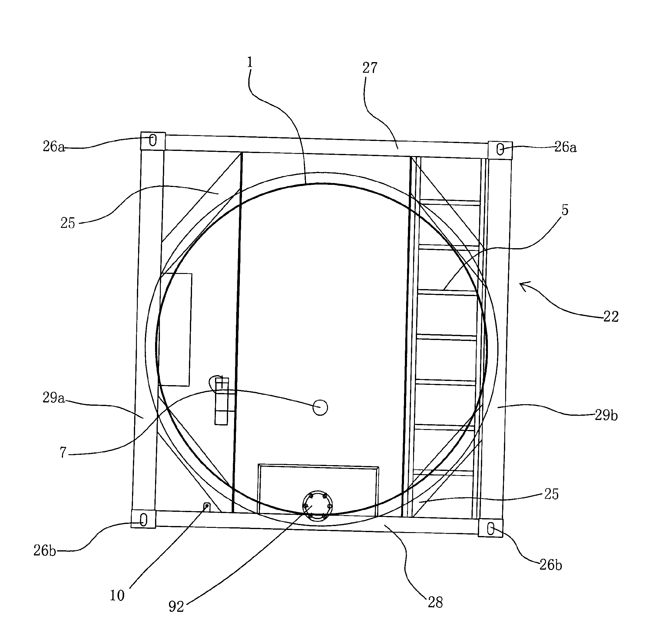
[0021] Such as figure 1 and figure 2 Shown in the figure, tank body 1; frame 2; front end frame 21; rear end frame 22; upper side beam 23; lower side beam 24; Beam 28; first column 29a; second column 29b; refrigeration system 3; heat insulation layer 4; ladder 5; walkway 6; Inlet and outlet valve 92; inlet and outlet valve 93; gas phase valve 94; steam valve 95;

[0022] This refrigerated tank container is suitable for road and sea transportation and intermodal transportation between these transportation methods. The carrying medium (such as beer, etc.) needs to maintain a certain temperature of non-dangerous liquid medium during transportation. It is mainly composed of frame 2, tank body 1, The refrigeration system 3 ...


PUM


Abstract

The invention provides a refrigerating tank container solving the problems of long distance transport and the like of liquid medium (such as beer and the like) which asks for lower temperature. The refrigerating tank container comprises a tank body and a frame assembled outside the tank body, wherein the frame is formed by connecting a front end frame, a rear end frame, an upper side beam, a lowerside beam, a diagonal bracing, an upper corner piece and a lower corner piece; a pipeline valve and a refrigerating system are assembled in the tank body, wherein the refrigerating system ensures that temperature in the tank body is kept within a certain temperature range; and the outer wall of the tank body is wound with multiple layers of heat insulation layers. The invention has the advantageof flexible transport, can be used in sea transport, highway transport and railway transport and can also be used in combined transport; in addition, the invention can keep the temperature of medium in the tank within a certain temperature range by the refrigerating system, thus realizing long distance transport of liquid medium which asks for lower temperature; the invention has flexible loadingand unloading, and the tank body can be loaded and unloaded upwards and downwards.

Description

technical field [0001] The invention relates to a container, in particular to a refrigerated tank container for liquid medium storage and transportation. Background technique [0002] The common way of transporting liquids in the past was to fix the tank container on the train by train, and the car on the cargo box. Tank containers for trains are round and relatively large, while tank containers for automobiles are oval and relatively small. If the same liquid, such as beer, is to be transported over a long distance, it must be filled by train into the brewery, then poured into the place of use after being transported to the destination, and then transported to the beer station or beer station after being filled by the car from the place of use. The user unit pours the beer into the beer storage warehouse, which cannot realize the intermodal transport of railways, highways, and waterways because it cannot be loaded and unloaded as a whole, and must go through multiple trans...

Claims


Application Information

Patent Timeline
Patent Type & Authority Applications(China)
IPC IPC(8): B65D88/74B65D90/00B65D90/06B65D90/10B65D90/20B65D90/22
Inventor 闻庆曹文红
Owner NINGBO MINGXIN CHEM MACHINERY
Why Eureka
Try Eureka