
Slip ring device

A slip ring device and slip ring technology are applied in the field of rotary kilns to meet usage requirements and prevent gaps or deformations

Active Publication Date: 2010-03-03
ZHONGYE-CHANGTIAN INT ENG CO LTD
View PDF0 Cites 8 Cited by
  • Summary
  • Abstract
  • Description
  • Claims
  • Application Information

AI Technical Summary

Problems solved by technology

[0006] Therefore, how to provide a slip ring device that can effectively prevent the slip ring from causing large gaps or deformation at the joint of the slip ring due to overheating and expansion of the rotary kiln shell, and also satisfy the installation problem of the slip ring, is an important issue. Technical problems to be solved by those skilled in the art

Method used


Image

  • Slip ring device
  • Slip ring device
  • Slip ring device

Examples


Embodiment Construction

[0024] The invention provides a thermocouple slip ring device, which is used to effectively prevent large gaps or deformation at the joint of the slip ring due to overheating and expansion of the rotary kiln cylinder, and can also meet the installation problem of the slip ring.

[0025] In order to facilitate the understanding of those skilled in the art, the structure and working principle of the slip ring device in the embodiment will be described in detail below with reference to the accompanying drawings.

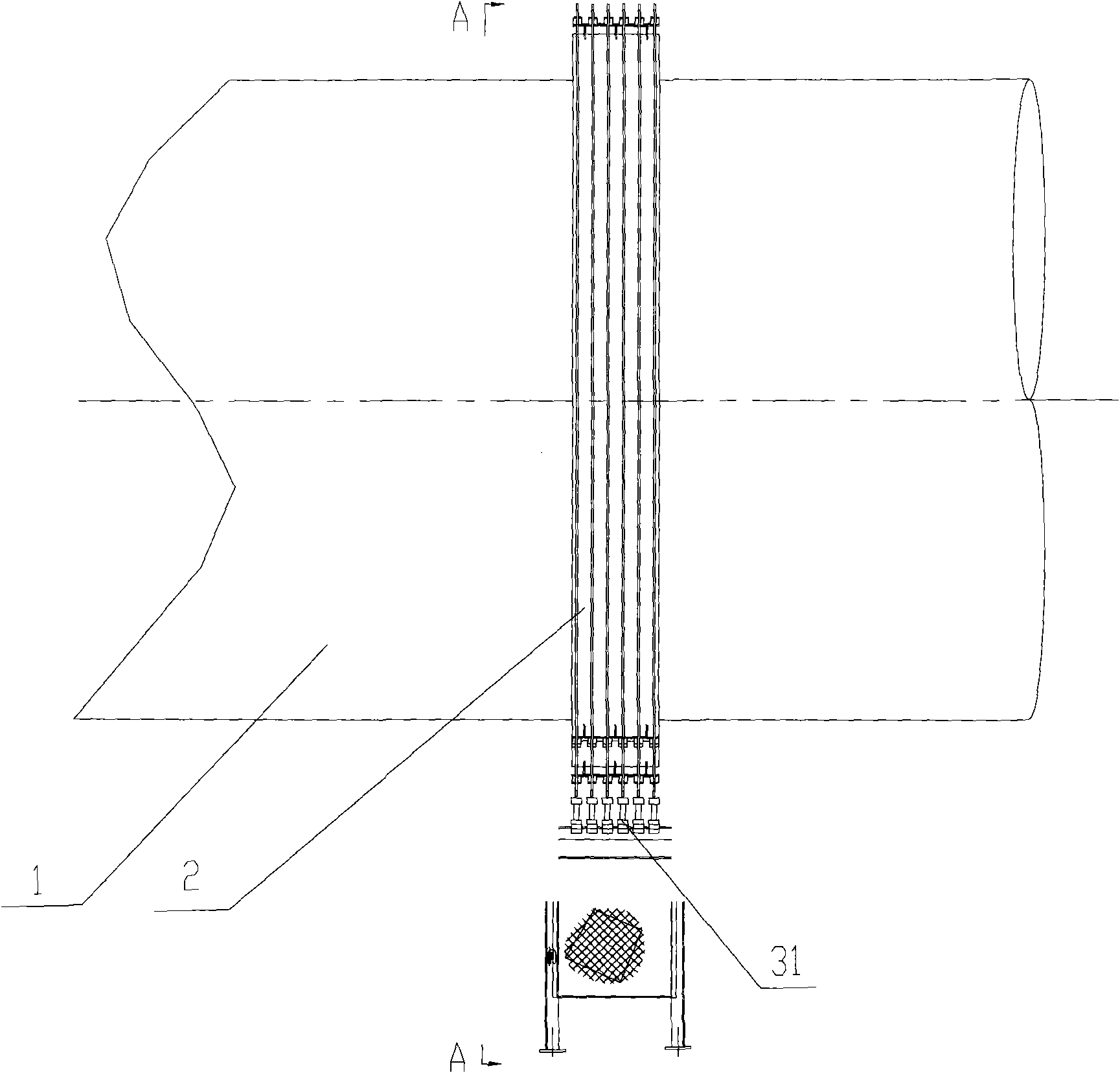
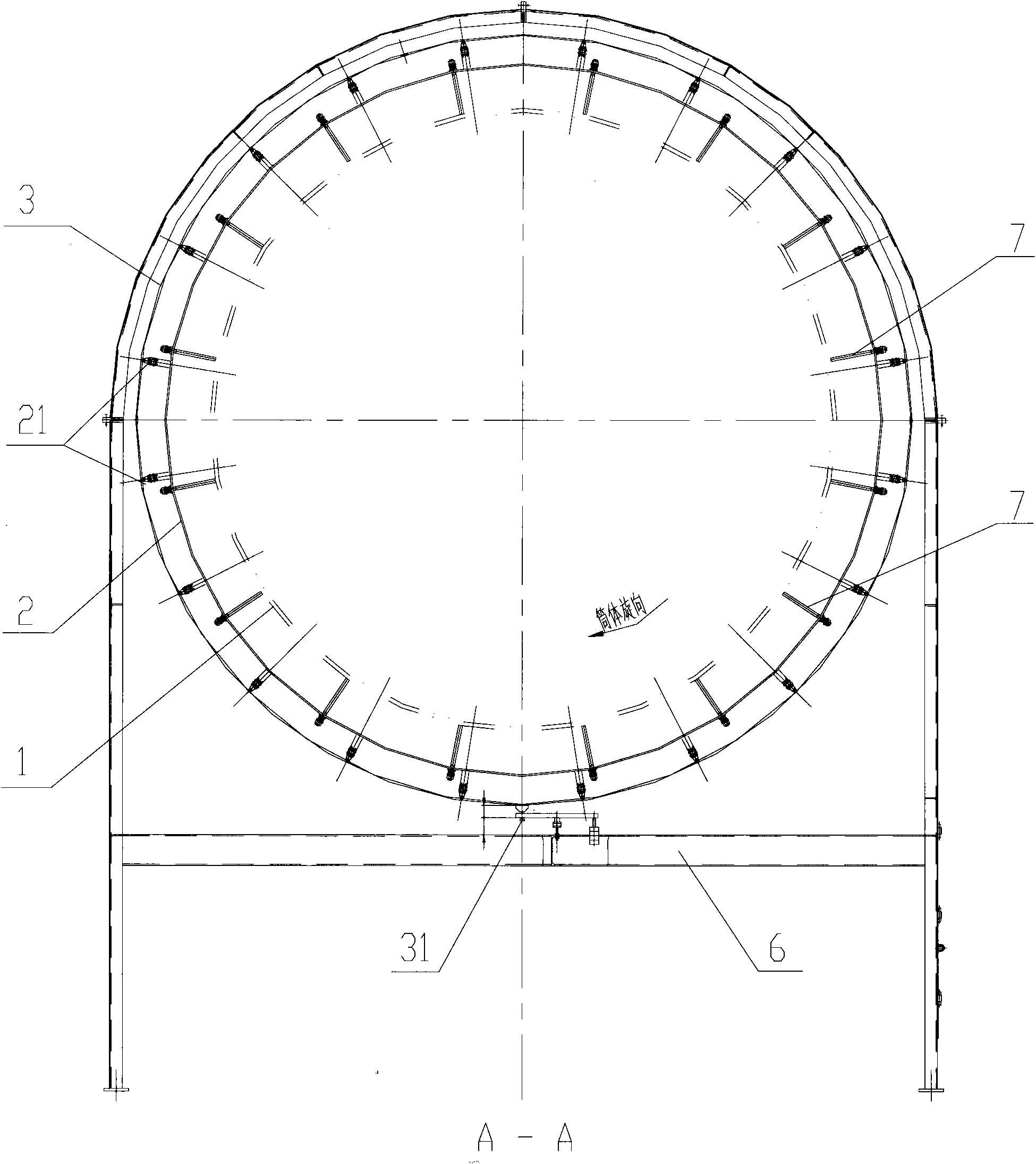
[0026] see figure 2 and image 3 , figure 2 It is the front view of the slip ring device according to the embodiment of the present invention; image 3 yes figure 2 Shown is the A-A sectional view.

[0027] The slip ring device in the embodiment of the present invention includes a heat insulating ring 2 fitted outside the rotary kiln shell 1 and at least one set of slip rings fitted outside the heat insulating ring 2 .

[0028] Each set of slip rings includes tw...


PUM


Abstract

A slip ring device comprises a heat insulation ring sheathed outside the barrel of a rotary kiln and at least one group of slip rings sheathed outside the heat insulation ring; each group of slip rings comprises two slip ring main bodies, wherein one slip ring main body is connected with a positive pole and the other slip ring main body is connected with a negative pole. The slip ring device provided by the invention can effectively avoid the problem of overheated slip rings and larger seam or deformation of the joints of slip rings caused by thermal expansion of the barrel of the rotary kiln.

Description

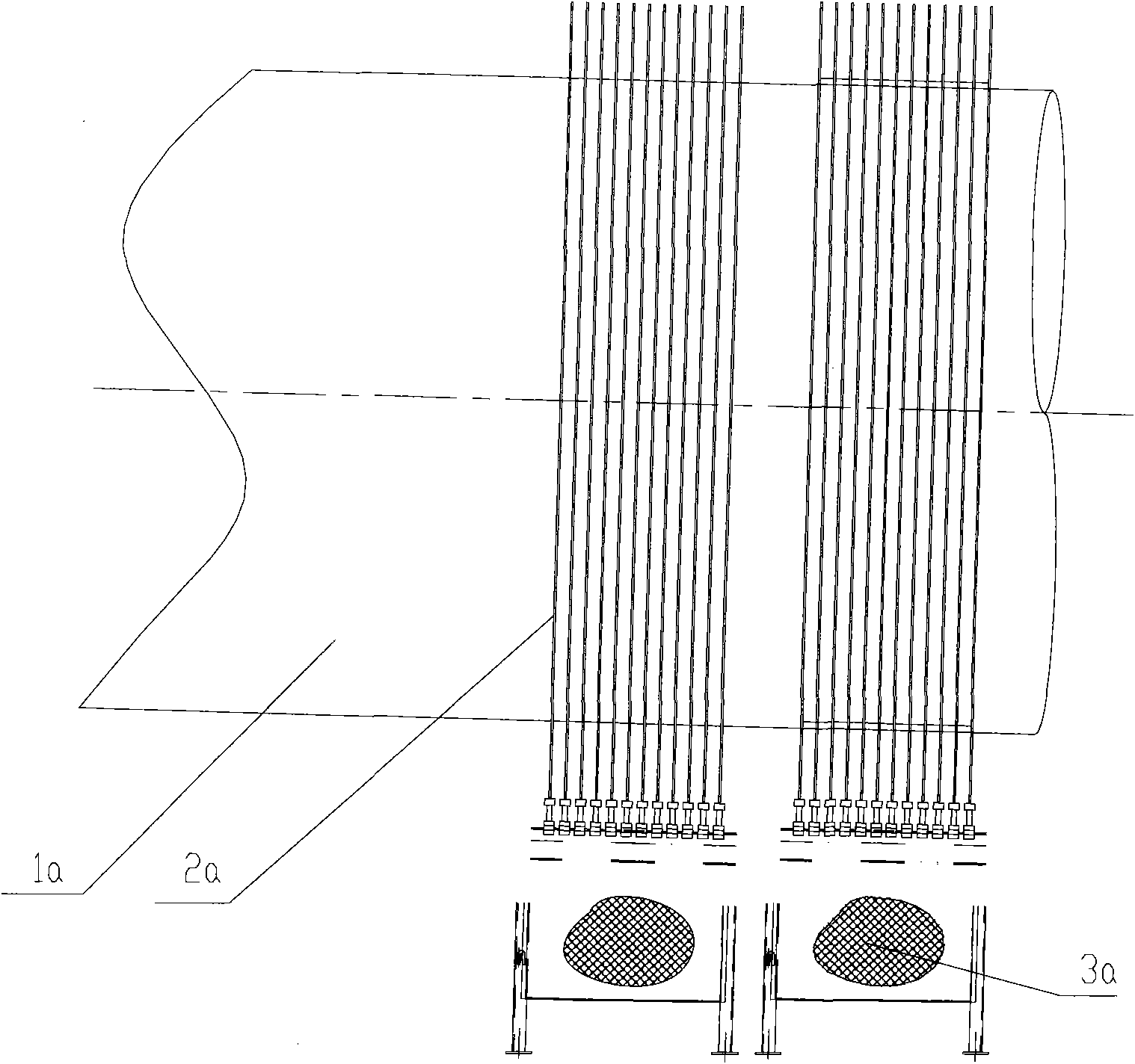
technical field [0001] The invention relates to a rotary kiln, in particular to a slip ring device. Background technique [0002] A fan that supplies air to the rotary kiln and a thermocouple that detects the temperature inside the rotary kiln are installed on the shell of the rotary kiln for direct reduction. In order to supply power to the fan and output the temperature signal of the thermocouple, a slip ring device is required. to realise. [0003] see figure 1 , which is a structural schematic diagram of an existing thermocouple slip ring device. The existing rotary kiln cylinder body 1a needs about 20 temperature values ​​at different positions, so 20 thermocouples (not shown in the figure) need to be installed at these 20 positions to measure the temperature at the corresponding positions. [0004] Since each thermocouple needs two slip rings 2a (one positive slip ring and one negative slip ring) to collect the temperature signal of the thermocouple, therefore, 40 s...

Claims


Application Information

Patent Timeline
Patent Type & Authority Applications(China)
IPC IPC(8): H01R39/08H01R39/14G01K7/02F27B7/20
Inventor 周慧玲戴传德
Owner ZHONGYE-CHANGTIAN INT ENG CO LTD
Learn More