
Method for designing ophthalmic progressive additional lens by utilizing meridian

A progressive multifocal and ophthalmic lens technology, applied in glasses/goggles, optics, instruments, etc., can solve problems such as single function requirements and inability to design progressive multifocal ophthalmic lenses suitable for different use occasions

Active Publication Date: 2010-03-03
SCHOOL OF OPHTHALMOLOGY & OPTOMETRY WENZHOU MEDICAL COLLEGE +2
View PDF0 Cites 44 Cited by
  • Summary
  • Abstract
  • Description
  • Claims
  • Application Information

AI Technical Summary

Problems solved by technology

At present, the progressive multifocal ophthalmic lenses designed at home and abroad are only suitable for a single functional requirement, and cannot be designed for progressive multifocal ophthalmic lenses suitable for different use occasions

Method used

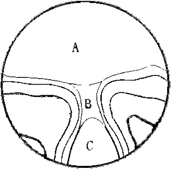

Image

  • Method for designing ophthalmic progressive additional lens by utilizing meridian
  • Method for designing ophthalmic progressive additional lens by utilizing meridian
  • Method for designing ophthalmic progressive additional lens by utilizing meridian

Examples


example 1

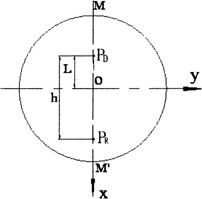
[0075] Example 1: The preset progressive multifocal ophthalmic lens has a far point lens power of 100 degrees, an addition power of 150 degrees between the far point of vision and the near point of vision, the lens channel length h=21 mm, and the distance point of vision A and the center of the lens The pitch of the dots L=7mm. The lens diameter is 60mm and the refractive index is 1.499.

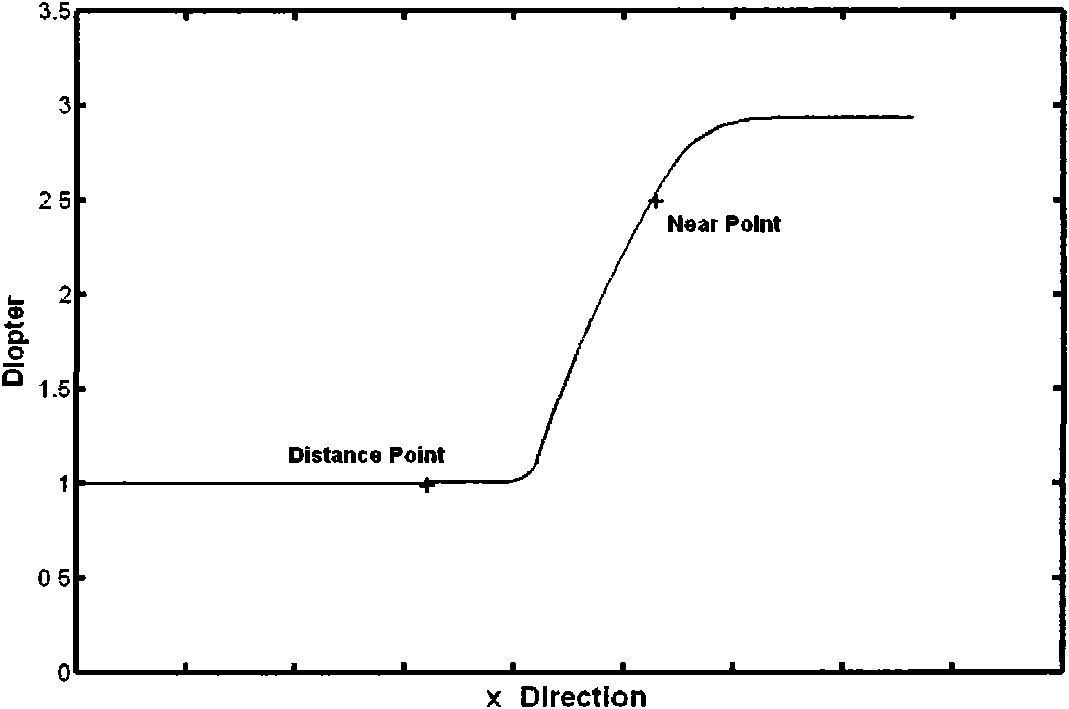
[0076] Figure 5 and Figure 6 They are the average sphere diagram of the progressive multifocal ophthalmic lens and the astigmatism distribution diagram of the progressive multifocal ophthalmic lens in Embodiment 1 of the present invention, respectively. Depend on image 3 It can be seen from the graph that the diopter along the meridian of the lens remains basically unchanged in the far vision zone, and gradually increases from the far vision point to the near vision zone. The diopter change coincides with the designed meridian, and the astigmatism and distortion are very small.

example 2

[0077] Example 2: Using the lens parameters described in Example 1, using the meridian diopter curve as attached Figure 7 , this curve is also calculated according to the above-mentioned meridian diopter change curve equation, but the values ​​of m and l are different from those in Example 1, so the meridian diopter curve is also different. The diopter changes almost linearly, and the diopter slowly tends to a stable value outside the far point and the near point, and tends to a stable value slowly outside the far point, and the diopter value is small, and then after the near point Tends faster to a smaller diopter value.

[0078] Figure 9 and Figure 10 They are the average sphere diagram of the progressive multifocal ophthalmic lens and the astigmatism distribution diagram of the progressive multifocal ophthalmic lens in Example 2 of the present invention, respectively.

[0079] It can be seen from Example 1 and Example 2 that although the design parameters of the lens ...


PUM

PropertyMeasurementUnit
Diameteraaaaaaaaaa

Abstract

The invention relates to a method for designing a lens, in particular to a method for designing an ophthalmic progressive additional lens by utilizing meridian. The method mainly comprises the following steps of: a) designing a meridian diopter variation curve of the ophthalmic progressive additional lens; and b) determining the surface shape of the ophthalmic progressive additional lens accordingto the meridian diopter variation curve. According to the visual demands of a wearer, the diopter distribution of the ophthalmic progressive additional lens is designed along the meridian, therefore,the method can be used for the design of multifunctional ophthalmic progressive additional lens; in addition, according to the meridian diopter variation curve, the method can determine the surface shape, the diopter and astigmation distribution of the ophthalmic progressive additional lens to better satisfy the needs of wearers.

Description

technical field [0001] The invention relates to a lens design method, in particular to a method for designing progressive multi-focus ophthalmic lenses using meridians. Background technique [0002] Progressive multifocal ophthalmic lenses use free-form surfaces to realize the continuous change of the focal power of the lens, and realize the natural connection between the surface shape and diopter of the far vision zone and the near vision zone through the transition zone where the diopter is continuously and gradually increased, so that different distances from far to near can be achieved. The field of view can be clearly imaged without breaks, and it overcomes the discontinuity of the field of view, broken images, blurred vision in the middle distance, and obvious differences between the far and near vision areas when people use bifocal mirrors to switch between the far and near vision areas. Therefore, progressive multifocal ophthalmic lenses are attracting more and more ...

Claims


Application Information

Patent Timeline
IPC IPC(8): G02C7/06G02B27/00
Inventor 吴泉英钱霖陈浩王媛媛余景池
Owner SCHOOL OF OPHTHALMOLOGY & OPTOMETRY WENZHOU MEDICAL COLLEGE
Learn More