Adjusting device for differential mechanism of straight flat seaming machine

A technology of a differential mechanism and an adjustment device, which is applied to the cloth feeding mechanism, sewing machine components, sewing equipment and other directions, can solve the problems of high cost, inconvenient use, complex structure, etc., and achieves low production cost, reasonable design and simple structure. Effect

Active Publication Date: 2012-07-04
浙江振盛缝制机械有限公司
View PDF7 Cites 4 Cited by
  • Summary
  • Abstract
  • Description
  • Claims
  • Application Information

AI Technical Summary

Problems solved by technology

[0004] The adjustment mechanism can change the feeding speed of the differential mechanism, but there are many parts, the structure is complex, and the cost is high; the use of many linkage mechanisms is inconvenient, and it will be difficult to effectively adjust the differential mechanism as the use time increases Feeding speed

Method used


Image

  • Adjusting device for differential mechanism of straight flat seaming machine
  • Adjusting device for differential mechanism of straight flat seaming machine
  • Adjusting device for differential mechanism of straight flat seaming machine

Examples


Embodiment 1

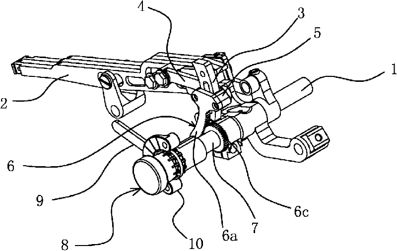
[0028] Such as figure 1As shown, the differential mechanism of the straight-through interlock sewing machine includes a differential bracket 2 arranged on the frame and a feed shaft 1 for driving the differential mechanism, and there is also a side-by-side arrangement with the differential bracket 2 The main tooth frame sheet and the needle guard tooth frame sheet 14, the differential tooth frame sheet 2 is provided with a differential feeding tooth, and the main tooth frame sheet is provided with a main feeding tooth. An arc-shaped differential crank 3 is fixed on the feeding shaft 1, and a connecting rod 4 is arranged between the differential crank 3 and the differential bracket piece 2, and one end of the connecting rod 4 is hinged with the differential bracket piece 2, The adjustment device is arranged at the other end of the connecting rod 4 and the differential crank 3, and includes a slider 5 that can slide along the differential crank 3, the other end of the connecting...

Embodiment 2

[0035] The general content of this embodiment is the same as that of Embodiment 1, the difference is that, as Figure 4 As shown, the adjustment assembly 8 in this embodiment includes a polygonal column 11 sleeved on the sleeve 7 and fixed in the circumferential direction. In this embodiment, a hexagonal shape is used. Of course, as another solution, a quadrangle or a cylinder can also be used. Pentagon, one side of the cylinder 11 is provided with a shaft sleeve 8c between the positioning gear 6c, and the other side of the cylinder 11 is provided with a fastener 2 8f for axially positioning the cylinder 11, and a fastener 2 8f It is axially screwed with the end face of the feeding shaft 1. As another solution, the column body 11 can be replaced by an outer hex nut. The user can effectively rotate the sleeve 7 by clamping the polygonal cylinder 11 with a wrench.

Embodiment 3

[0037] The general content of this embodiment is the same as that of Embodiment 1, the difference is that, as Figure 5 As shown, the adjustment assembly 8 includes a plurality of positioning surfaces 12 for wrench positioning on the sleeve 7 by means of material removal, and the end surface of the sleeve 7 is provided with a fastener 2 8f that can block its outward movement. Part two 8f is axially screwed with the feed shaft 1 end face. In this solution, the user directly uses a wrench to clamp the positioning surface 12 on the sleeve 7 to rotate the positioning gear 6c on the sleeve 7, and the fastener 2 8f mainly plays a role in limiting the axial position of the sleeve 7. effect.


PUM


Abstract

The invention provides an adjusting device for a differential mechanism of a straight flat seaming machine, belonging to the field of mechanical technology. The invention solves the technical problem that an adjusting device of the prior differential mechanism has complicated structure, high cost, inconvenient use and the like. In the adjusting device for the differential mechanism of the straight flat seaming machine, a differential crankshaft is fixed on a feeding shaft, a linkage rod is arranged between the differential crankshaft and a differential tooth frame sheet, and one end of the linkage rod is articulated with the differential tooth frame sheet. The adjusting device is arranged on the other end of the linkage rod and the differential crankshaft, comprising a slide block capableof sliding along the differential crankshaft, the other end of the linkage rod is articulated with the slide block, the slide block is provided with a positioning structure capable of sliding along the differential crankshaft when needing the adjustment, and after the adjustment is finished, the slide block is fixed on the differential crankshaft to be stationary. The adjusting device can effectively adjust the feeding speed of the differential mechanism and has simple structure and reasonable design. The differential crankshaft is provided with a scale board that can achieve measurable adjustment.

Description

technical field [0001] The invention belongs to the technical field of machinery, and relates to an adjusting device for a differential mechanism, in particular to an adjusting device for a differential mechanism of a straight-tube interlock sewing machine. Background technique [0002] Nowadays, there are many kinds of clothing, and many details, such as the collar of the T-shirt, the hemming of the cuffs of the clothes, and the hemming of the trousers, are often sewed by workers on ordinary sewing machines by hand, so that the production efficiency is relatively high. Low and relatively labor-intensive. In order to improve these defects, some manufacturers have provided differential mechanisms on sewing machines to carry out differential auxiliary feeding of clothing materials, so as to improve the production efficiency of workers. However, for different sewing machine spindle speeds, the sewing speed is different, so the required differential feeding speed is also differ...

Claims


Application Information

Patent Timeline
Patent Type & Authority Patents(China)
IPC IPC(8): D05B27/08
Inventor 董伟弦王以志
Owner 浙江振盛缝制机械有限公司
Why Eureka
Try Eureka