
Cutter frame mechanism for processing spherical surface roller

A technology of spherical roller processing and tool rest, which is applied in metal processing equipment and other directions, can solve problems such as waste and complicated cost of components, and achieve the effects of easy processing, good wear resistance, and simplified part of the structure

Inactive Publication Date: 2010-02-17
WUXI YIJIATONG PRECISION MACHINERY MFG
View PDF0 Cites 1 Cited by
  • Summary
  • Abstract
  • Description
  • Claims
  • Application Information

AI Technical Summary

Problems solved by technology

There are also some tool holders that use springs to push the clamp forward when the clamp moves backward under the action of the clamping screw. In the manufacturing process of such clamps, there is a problem of cost waste due to the complexity of the parts

Method used


Image

  • Cutter frame mechanism for processing spherical surface roller

Examples


Embodiment Construction

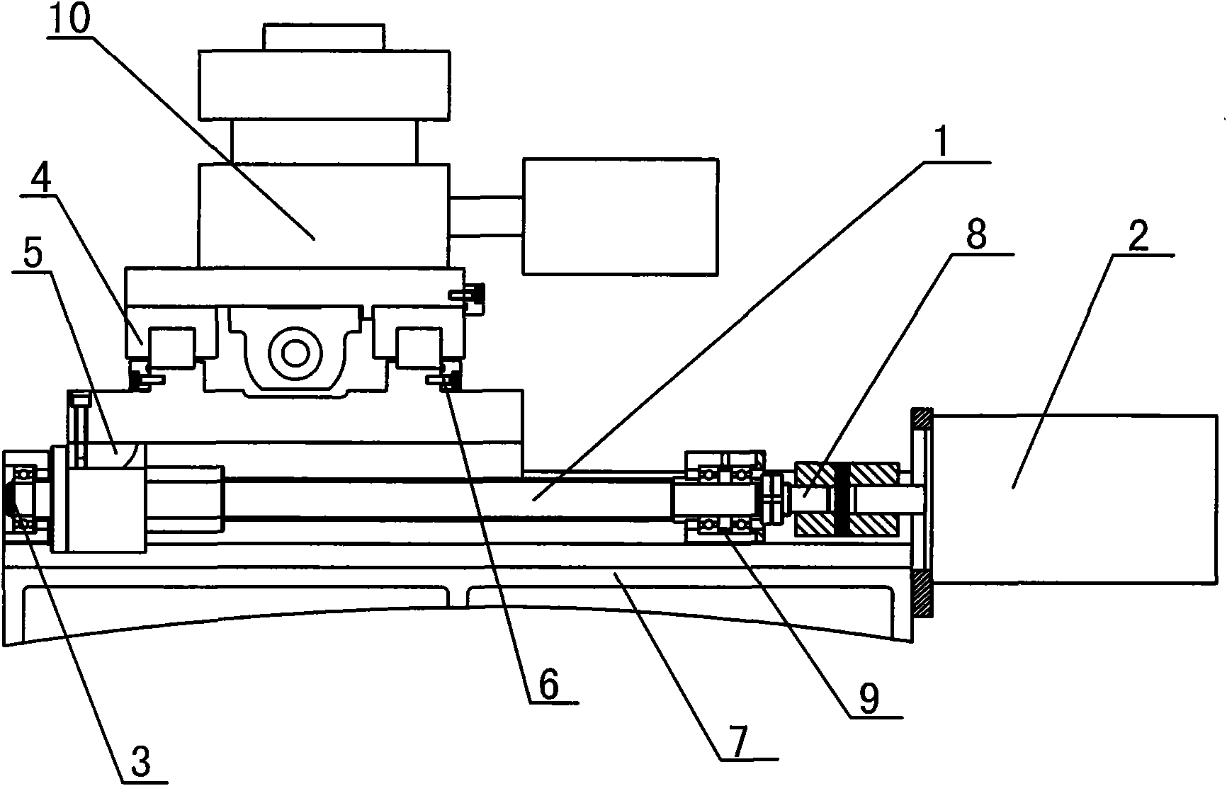
[0011] Such as figure 1 As shown, the tool holder mechanism for spherical roller processing according to the present invention includes a ball screw 1 and a rolling guide 4, the ball screw 1 is arranged on the upper side of the chassis 7, and one part of the ball screw 1 The drive unit 2 is connected to the side, and the linkage rod 8 is connected between the drive unit 2 and the ball screw 1, and the linkage rod 8 is connected with the transmission assembly 9; the other side of the ball screw 1 is provided with a stop Ring 3, the upper side of the ball screw 1 is provided with a rolling guide 4, the lower end of the rolling guide 4 is provided with a bolt 6, and the upper part of the rolling guide 4 is provided with a cutting unit 10; the upper side of the ball screw 1 Connect pin 5. The rolling guides are 4 linear sliding guides with good wear resistance.


PUM


Abstract

The invention relates to a cutter frame mechanism for processing a spherical surface roller, comprising a ball screw rod and a rolling guide rail. The ball screw rod is arranged on the upper side of abottom frame, one side of the ball screw rod is connected with a driving unit, a link rod is connected between the driving unit and the ball screw rod and is connected with a driving assembly, and the upper side of the ball screw rod is provided with the rolling guide rail. The invention has the advantages that the partial structure is simplified, a moving guide rail is a linear sliding guide rail, and the cutter frame mechanism has favorable wear resistance and lower cost and is convenient to process the spherical surface roller.

Description

technical field [0001] The invention relates to the field of machine tool equipment, in particular to a tool holder mechanism for spherical roller processing. Background technique [0002] A typical tool holder mechanism utilizes a tapered hole whose axis is offset from the threaded portion of the locking pin receiving hole to tilt the locking pin adjacent to the cutting bit. There are also some tool holders that use springs to push the clamp forward when the clamp moves backward under the action of the clamping screw. In the manufacturing process of this type of clamp, there is a problem of cost waste due to the complexity of the parts. Contents of the invention [0003] In view of the above defects, the purpose of the present invention is to provide a tool holder mechanism for spherical roller processing with simple components, good wear resistance and stable slide rail, so as to overcome many shortcomings of the prior art. [0004] To achieve the above object, the pres...

Claims


Application Information

Patent Timeline
Patent Type & Authority Applications(China)
IPC IPC(8): B23B21/00
Inventor 何民权
Owner WUXI YIJIATONG PRECISION MACHINERY MFG
Learn More