
Structure for manually orienting vertical wind-guiding vanes of indoor units of wall-mounted air conditioners

A technology of wall-mounted air conditioners and air guide vanes, applied in the direction of airflow control components, etc., can solve the problems of poor orientation and poor cooperation of vertical air guide vanes, and achieve the effect of good cooperation, free adjustment, accurate and stable orientation

Inactive Publication Date: 2010-02-03
LG ELECTRONICS (TIANJIN) APPLIANCES CO LTD
View PDF0 Cites 3 Cited by
  • Summary
  • Abstract
  • Description
  • Claims
  • Application Information

AI Technical Summary

Problems solved by technology

[0026] However, in the existing manual orientation structure of the vertical wind deflector vane, when the protrusion 12' turns to the edge corrugations of a plurality of vertical parallel corrugations 20', since the protrusions are formed in the radial direction of the disc, the plurality of corrugations are formed in the radial direction of the disc. Vertical and parallel directions, therefore, due to the azimuth deflection of the protrusion 12' and the rib 20', the coordination between the two is not good, resulting in poor orientation of the vertical wind guide vanes

Method used


Image

  • Structure for manually orienting vertical wind-guiding vanes of indoor units of wall-mounted air conditioners
  • Structure for manually orienting vertical wind-guiding vanes of indoor units of wall-mounted air conditioners
  • Structure for manually orienting vertical wind-guiding vanes of indoor units of wall-mounted air conditioners

Examples


Embodiment Construction

[0051] 20', 20-convex

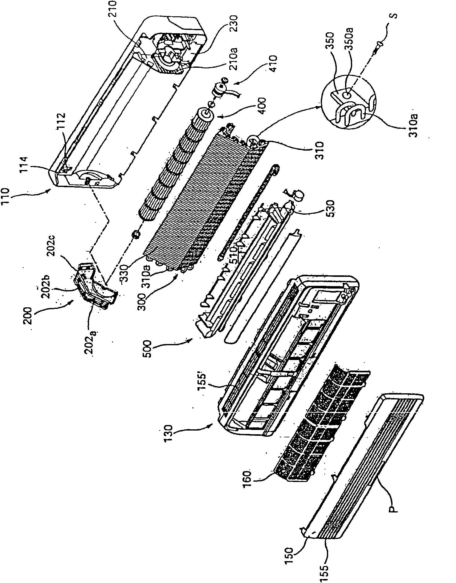
[0052] In order to further illustrate the content, technical solutions and characteristics of the present invention, the following examples are given and described below in conjunction with the accompanying drawings: as Image 6 , 7 , 8, the technical scheme of the vertical guide vane manual orientation structure of the wall-mounted air-conditioning indoor unit of the present invention includes: the vertical guide vane rotating shaft frame 3 installed on the upper and lower parts of the exhaust port; The vertical wind guide vanes 2 in each shaft hole of the wind guide vane rotating shaft frame; the connecting rod 7 connecting the steering shaft of each vertical wind guide vane with the shaft hole; it is characterized in that: a shaft on the right side of the connecting rod and the side of the water tray In the hole 11, there is also a vertical guide vane manual orientation knob 1 connected with a shaft. The water receiving tray wall bel...


PUM


Abstract

The invention relates to an air conditioner, in particular to a structure for manually orienting vertical wind-guiding vanes of indoor units of wall-mounted air conditioners, which solves the problemthat the prior vertical wind-guiding vane is not good in orientation. A technical scheme comprises wind-guiding-vane rotation shaft brackets which are arranged on the upper and lower parts of an exhaust port, vertical wind-guiding vanes which are arranged in shaft holes of the wind-guiding-vane rotation shaft brackets through rotation shafts, and a connecting bar which is connected with a direction-adjusting shaft of the vertical wind-guiding vanes through the shaft holes. The structure is characterized in that a shaft hole on the right side of the connecting bar and the side of a water-receiving plate is connected with a manual orienting knob of the vertical wind-guiding vanes through a shaft; two convex ridges matched with the water-receiving plate for orientation are designed on the wall of the water-receiving plate under the knob; and the orienting knob consists of a disk provided with a rotation shaft hole in the center, a handle formed at one end of the diameter of the disk, a plurality of protrusions formed under the periphery of the disk on the base part of the handle, and the vertical wind-guiding vanes formed at the other end of the diameter of the disk. The structure isused in the indoor units of the wall-mounted air conditioner to ensure accurate stable orientation of the vertical wind-guiding vanes.

Description

technical field [0001] The invention relates to an air conditioner, in particular to a manual orientation structure for vertical wind guide blades of a wall-mounted air conditioner indoor unit with stable orientation. Background technique [0002] Generally speaking, an air conditioner is a device that maintains the indoor air in the desired optimal state. For example, when the indoor temperature is high in summer, it sends cool air with low temperature to lower the indoor temperature, and when the indoor temperature is low in winter, it sends warm air with high temperature to keep warm. [0003] In addition, other uses of air conditioners also include various functions such as adjusting indoor humidity and air purification. [0004] Air conditioners are roughly divided into integrated type and split type. The integral type air conditioner is constituted as a unit as a whole, and the split type air conditioner is composed of an indoor unit installed in the space where the ...

Claims


Application Information

Patent Timeline
IPC IPC(8): F24F13/14
Inventor 杨玉华
Owner LG ELECTRONICS (TIANJIN) APPLIANCES CO LTD
Learn More