Air conditioner

A technology of air conditioners and heat exchangers, which is applied in air conditioning systems, machines/engines, space heating and ventilation, etc., and can solve problems such as difficulty in forming a compact, broken fan, and increased ventilation resistance

Active Publication Date: 2010-01-20
MITSUBISHI ELECTRIC CORP
View PDF0 Cites 15 Cited by
  • Summary
  • Abstract
  • Description
  • Claims
  • Application Information

AI Technical Summary

Problems solved by technology

However, when the blower uses a centrifugal fan whose outer diameters of the main plate and the side plate are substantially the same, the blown air direction of the centrifugal fan is a horizontal direction perpendicular to the axis, so when the centrifugal fan is installed inside the air conditioner body, Down, the blown airflow on the side plate side and the blown airflow on the main board side interfere, the ventilation resistance increases, and the noise increases. Therefore, it is necessary to form a state where the fan is protruded toward the bottom of the air conditioner body.
Therefore, it is necessary to install the ceiling panel in a state protruding from the ceiling surface, and it is difficult
In addition, if the suction distance between the top plate of the body and the suction port of the centrifugal fan is too narrow, the ventilation resistance will increase, and the difference in flow velocity near the wind deflector and the top plate side of the body will cause a biased flow, turbulent suction airflow, and increased noise.
And if the above-mentioned suction distance is too large, the height of the body will increase
Furthermore, before installation, when the main body and the ceiling panel are separated, since the centrifugal fan is installed in a state protruding from the main body, the centrifugal fan is damaged during transportation.
Moreover, in order to prevent the fan from being damaged, a large amount of packaging material needs to be used around the fan protruding from the main body, which is not conducive to environmental protection

Method used


Image

  • Air conditioner
  • Air conditioner
  • Air conditioner

Examples


no. 1 approach

Use the following Figure 1 to Figure 11 An air conditioner according to a first embodiment of the present invention will be described.

figure 1 It is an air conditioner according to the first embodiment of the present invention, and is a diagram of the installation state of the air conditioner viewed from a room, figure 2 It is a longitudinal sectional view in the setting state of the air conditioner, image 3 It is a perspective view when the air conditioner body and ceiling panel are attached, Figure 4 yes figure 2 A longitudinal sectional view of the air conditioner, Figure 5 yes Figure 4 The horizontal sectional view on the k1~k4 section indicating line in Figure 6 is the perspective view of the wind deflector, Figure 7 It is a perspective view viewed from the side of the main board of the centrifugal fan, Figure 8 yes Figure 7 Longitudinal projection of the Figure 9 yes Figure 8 Blade sectional view and local enlarged view on the line a-a, Figure ...
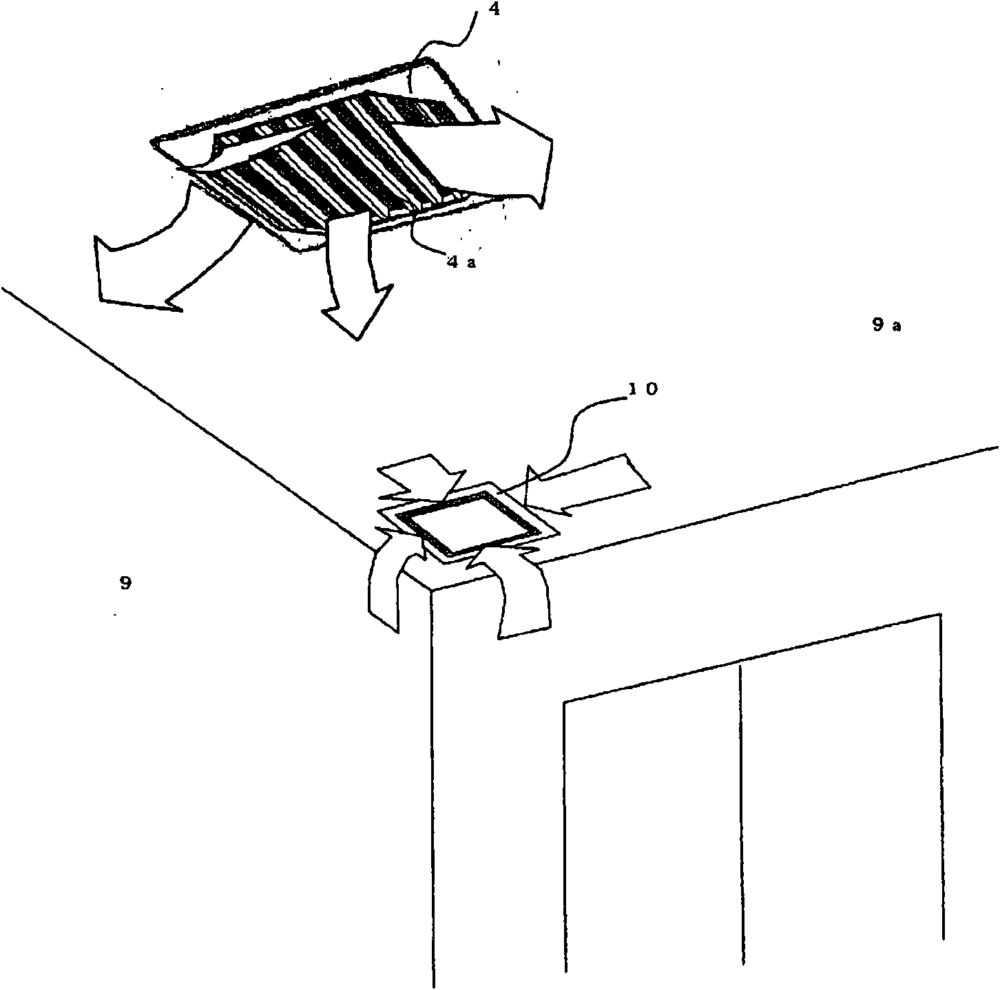
no. 2 approach

Below, use Figure 15 to Figure 17 An air conditioner according to a second embodiment of the present invention will be described.

Figure 15 It is the air conditioner of the second embodiment, and is a perspective view when the air conditioner body and the ceiling panel are attached, Figure 16 yes Figure 15 Longitudinal sectional view of the air regulator on J1-J2-J3, Figure 17 yes Figure 16 Horizontal cross-sectional views of half of each height position of L1-L2 and L3-L4. In addition, main configurations and corresponding symbols are the same as those in the first embodiment.

[0039] Such as Figure 15 As shown, the main body of the air conditioner has a rectangular parallelepiped shape, and a rectangular main body plate 4 is provided at the lower part of the main body 1 . and, if Figure 16 , Figure 17 As shown, the body side suction port 1a is provided on the body side wall 1b of the air conditioner body 1, and the body top plate side suction port 1d is pr...

no. 3 approach

Use the following Figure 18 to Figure 20 An air conditioner according to a third embodiment of the present invention will be described.

Figure 18 It is a perspective view at the time of attaching the air conditioner main body and the ceiling panel of the third embodiment, Figure 19 yes Figure 18 longitudinal section view of Figure 20 yes Figure 19 Horizontal sectional view on k1-k2-k3-k4. In addition, main configurations and corresponding symbols are the same as those of the first embodiment.

exist Figure 18 Among them, the air outlet 4a of the main body plate 4 is formed in a substantially square shape, and the centrifugal fan 8 is not easily seen from directly below the main body plate 4 from the center plate 4b at the center.

[0043] and, if Figure 19 As shown, the outer frame of the main body plate 4 is fixed on the main body 1 to form the bottom surface of the main body, and the central plate 4 at the central part of the main body plate 4 can be rotatabl...


PUM


Abstract

An air conditioner exhibiting high product reliability and transportability during transportation, not imposing a sense of oppression to a resident because of low noise, and being packed in less packing material as compared with conventional one. A centrifugal fan mounted on an air conditioner is shaped to have the following relation; the outside diameter of the side plate of the centrifugal fan > the side plate side outside diameter at the trailing edge of the blade > the main plate side outside diameter at the trailing edge of the blade >= the outside diameter of the main plate. The trailing edge of the blade is located on the inside of a line, which connects the joint of the trailing edge of the blade to the main plate, and the joint of the trailing edge of the blade to the side plate when viewed from the axis of rotation, and a distance to the axis of rotation becomes longer from the main plate toward the side plate.

Description

technical field [0001] The invention relates to an air conditioner whose main body is arranged inside a ceiling for cooling, heating, dehumidification, air purification and humidification. Background technique [0002] For example, in the air conditioner described in Patent Document 1, a ceiling surface suction port for sucking indoor air in the room into the ceiling is provided at a position separated from the air conditioner body of the ceiling, and a suction port is provided on the side wall of the body. The main body suction port is provided with a filter on the main body suction port, and a heat exchanger is arranged opposite to the main body suction port. And, the air blower is installed in the space surrounded by the air guide plate and the ceiling panel. Only the ceiling panel outlet is provided on the ceiling panel installed at the lower part of the main body. [0003] By forming in this way, the ceiling surface suction port for sucking air into the room is separa...

Claims


Application Information

Patent Timeline
IPC IPC(8): F04D29/28F04D29/30F24F1/00F24F1/0047F24F1/0063
CPCF04D29/444F24F2001/0037F04D29/281F04D25/12F04D29/30F04D29/667F24F7/007F24F1/0007F04D29/441F24F1/0022F04D17/06F24F1/0047F24F1/0063F04D29/626F24F1/00F24F7/065F24F13/06F24F7/06
Inventor 池田尚史竹原奈穗堤博司山谷贵宏西宫一畅川乘幸彦
Owner MITSUBISHI ELECTRIC CORP
Why Eureka
Try Eureka