
Driving circuit of high-voltage current transformer

A drive circuit and converter technology, applied in the field of high-voltage converters, can solve problems such as no successful cases and no literature reports, and achieve accurate and reliable drive functions, good economic and social benefits, flexible and adjustable IGBT overcurrent and The effect of short circuit protection

Inactive Publication Date: 2010-01-20
CRRC YONGJI ELECTRIC CO LTD
View PDF0 Cites 13 Cited by
  • Summary
  • Abstract
  • Description
  • Claims
  • Application Information

AI Technical Summary

Problems solved by technology

The drive circuit of the high-voltage converter is the key core component in the converter device, which can provide drive signals and protection circuits. There are no successful cases of this technology in China, and there are no relevant literature reports.

Method used


Image

  • Driving circuit of high-voltage current transformer
  • Driving circuit of high-voltage current transformer

Examples


Embodiment Construction

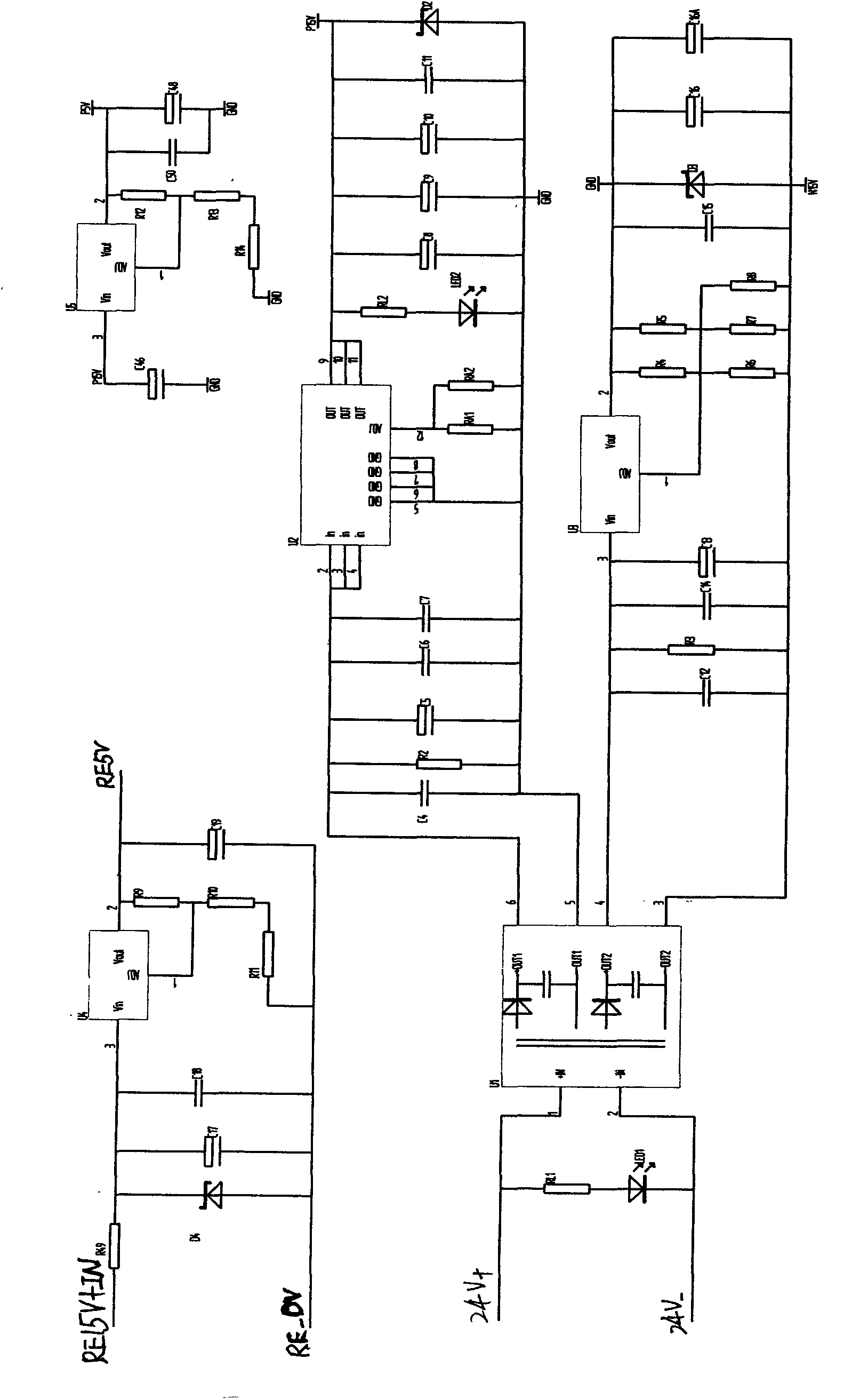
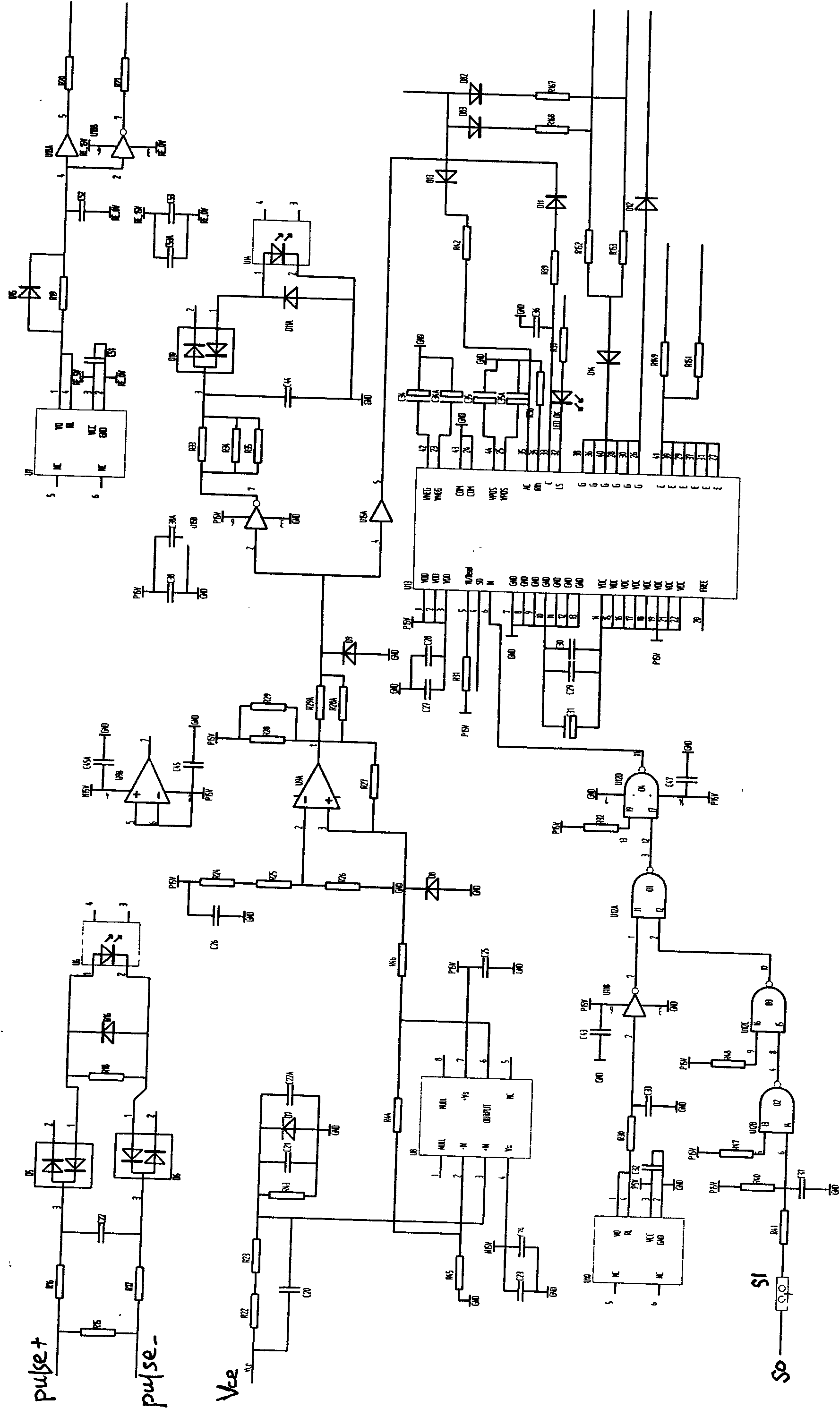
[0009] The driving circuit of the high-voltage converter includes a driving circuit, a power circuit, and a protection circuit. The power circuit includes a high-voltage isolation chip U1, the input terminal of the high-voltage isolation chip U1 is connected to the 24VDC input power supply, and the output terminal of the high-voltage isolation chip U1 A +15V power supply circuit containing a switching power supply chip U2 and a -15V power supply circuit containing an adjustable voltage regulator (device) chip U3 are connected. The +5V power supply circuit of the chip U4 and the +5V power supply circuit containing the adjustable voltage regulator chip U5 whose input terminal is connected to the output power supply terminal of the +15V power supply circuit; The input end is connected with a trigger pulse receiving circuit, the trigger pulse receiving circuit includes a first optical fiber transmitter U6 and a first optical fiber receiver U10, the output end of the first optical f...


PUM


Abstract

The invention relates to a high-voltage current transformer, in particular to a driving circuit of the high-voltage current transformer. Thanks to the invention, the problem that at present no well-developed driving circuit is provided for high-voltage current transformers can be solved. The driving circuit of the high-voltage current transformer comprises a driving circuit, a power circuit and a protecting circuit. Apart from the self characteristics of the circuits, the driving circuit of the high-voltage current transformer is substantially characterized in that fiber optic transmitters and fiber optic receivers are used in the driving circuit and the protecting circuit; a high-voltage isolating chip is used in the power circuit; therefore the high-voltage isolation of the driving circuit of the high-voltage current transformer from other circuits is effectively realized, and the other circuits connected with the driving circuit are effectively protected against being possibly damaged by the high voltage and the large current, which flow past a high-voltage IGBT in the high-voltage current transformer, through the driving circuit. The driving circuit can achieve 10 kV of electric isolation, feed back the voltage status of a main loop and protect the safe performance of an IGBT power module. The driving circuit is successfully assembled in a four quadrant and an inversion module of a motor train unit.

Description

technical field [0001] The invention relates to a high-voltage converter, in particular to a driving circuit of a high-voltage IGBT in the high-voltage converter, in particular to a driving circuit of the high-voltage converter. Background technique [0002] According to international practice and my country's national standards for the division of voltage levels, when the power supply voltage is ≥ 10kV, it is called high voltage, and when it is 1kV ~ 10kV, it is called medium voltage. But we also customarily refer to motors with a rated voltage of 6kV or 3kV as "high voltage motors". High-voltage motors are widely used in enterprises and railway fields. Therefore, we call the converters driving 1-10kV AC motors high-voltage converters. However, the speed regulation and starting methods in our country are still very backward, which wastes a lot of energy and causes low mechanical life. Therefore, the benefits and potentials of popularizing and applying high-voltage frequen...

Claims


Application Information

Patent Timeline
IPC IPC(8): H02M3/155H02M1/32
Inventor 陈广泰宋春龙张晋芳
Owner CRRC YONGJI ELECTRIC CO LTD
Learn More