
Hybrid power plant and method of controlling such a power plant

A control method and engine technology, which are applied in the directions of engine control, gas turbine power plant, power plant, etc., can solve the problem of increasing fuel consumption rate and achieve the effect of reducing fuel consumption rate

Active Publication Date: 2010-01-20
EUROCOPTER
View PDF0 Cites 23 Cited by
  • Summary
  • Abstract
  • Description
  • Claims
  • Application Information

AI Technical Summary

Problems solved by technology

[0022] Thus, most of the time, such a gas turbine produces much less than its maximum power, which results in an increase in its specific fuel consumption

Method used


Image

  • Hybrid power plant and method of controlling such a power plant
  • Hybrid power plant and method of controlling such a power plant
  • Hybrid power plant and method of controlling such a power plant

Examples


Embodiment Construction

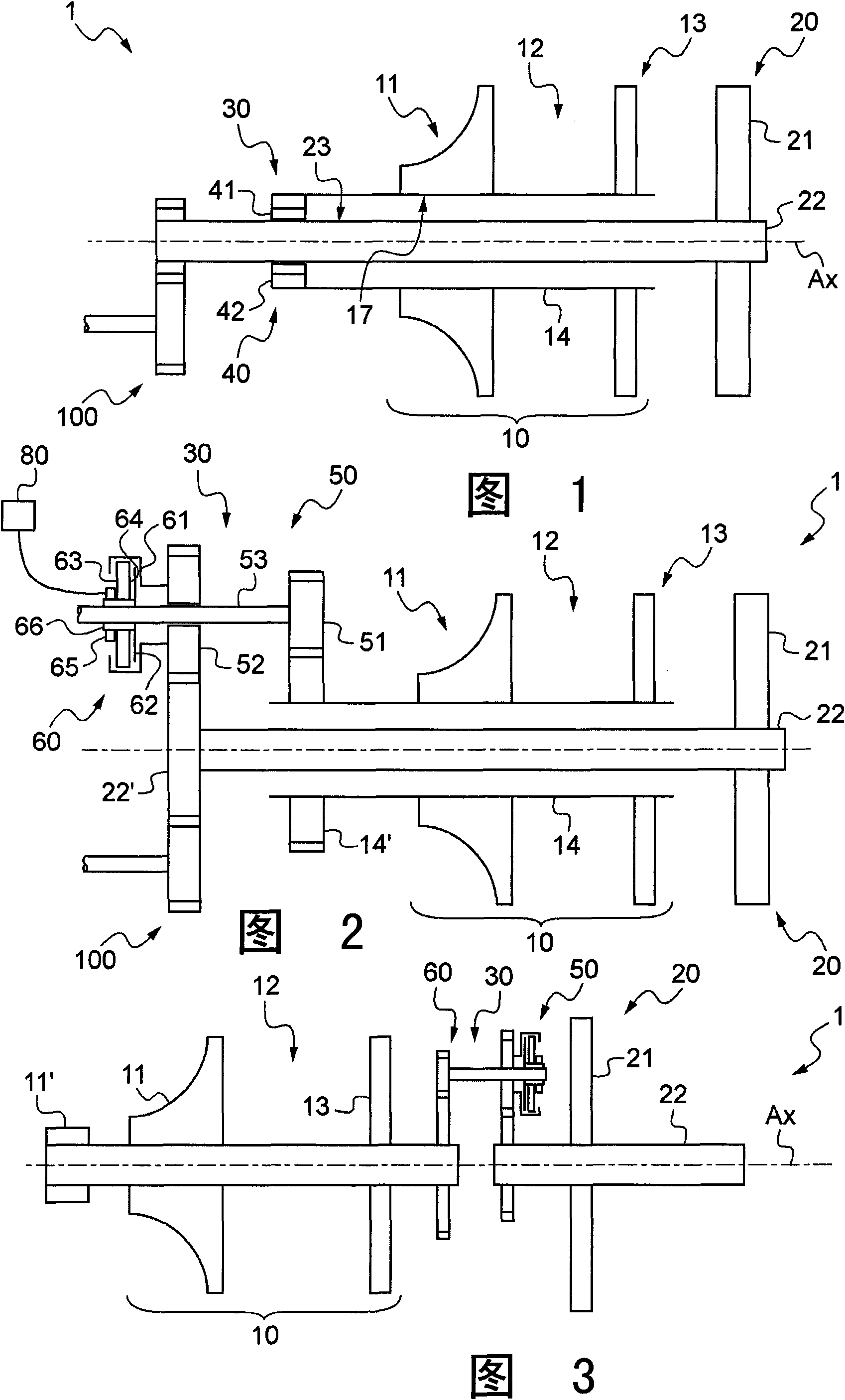
[0087] Figures 1 to 3 An innovative combined gas turbine 1 is shown which is suitable for use in an engine arrangement as claimed in the claims.

[0088] No matter in which embodiment, the combined gas turbine 1 includes a gas generator 10 and subsequent working components 20 in sequence along the direction of air flowing through the combined gas turbine 1 .

[0089] Along the direction of air flow through the combined gas turbine 1 , the gas generator is conventionally provided with at least one compressor 11 , a combustion chamber 12 , and at least one expansion turbine 13 connected to the compressor 11 via a main shaft 14 .

[0090] It should be seen that figure 1 with 2 Both show a single compressor 11, while image 3 An axial compressor 11' is shown followed by a centrifugal compressor 11.

[0091] It should be understood that the number of compressors and expansion turbines may be optimized according to requirements, without limiting the scope of the invention.

[...


PUM


Abstract

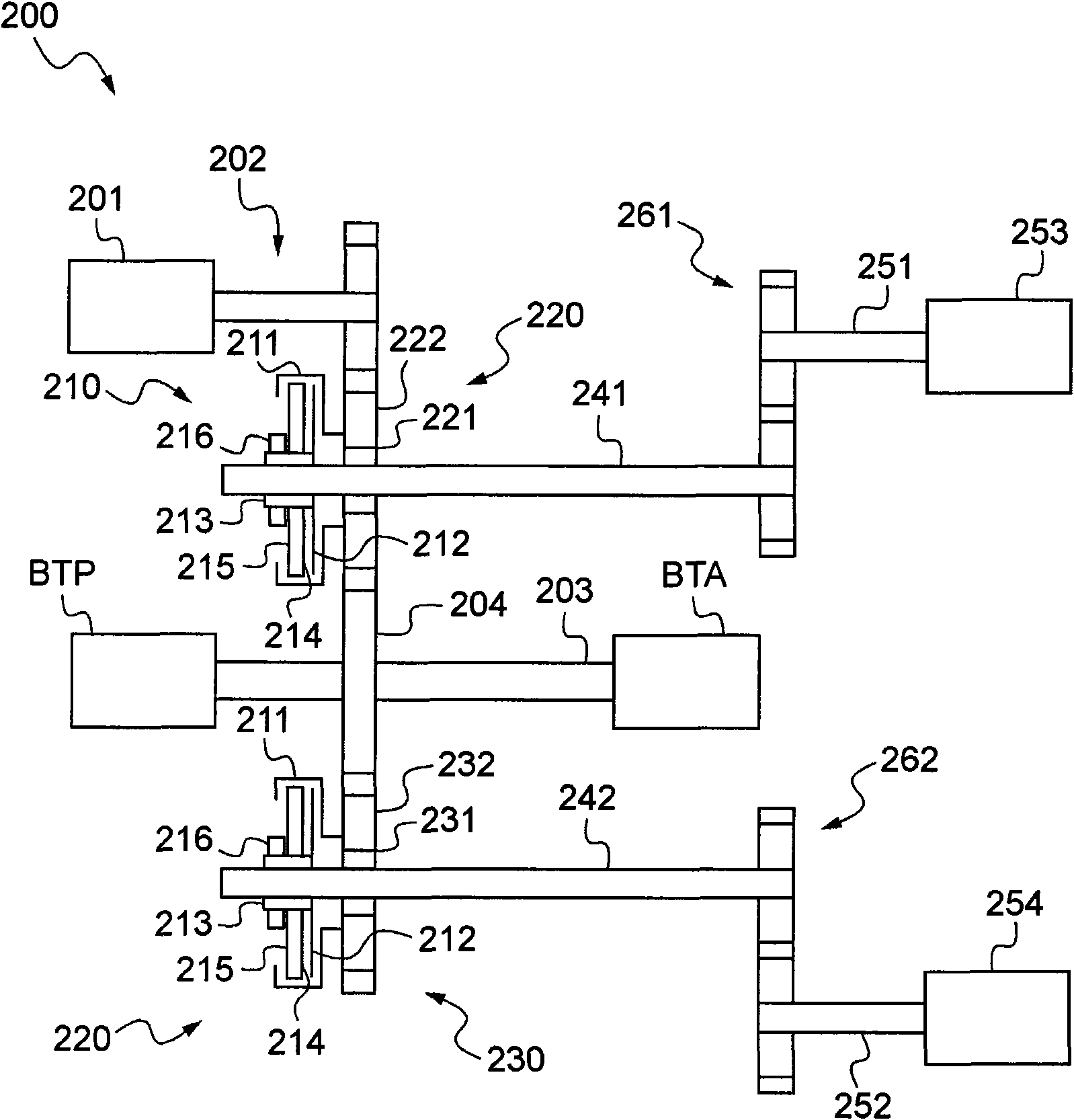
A hybrid engine installation (200) includes drive element (204) suitable for driving a mechanical element (BTP, BTA) in rotation. In addition, the hybrid engine installation is remarkable in that it includes at least one gas turbine (253, 254) and at least one electric motor (201) mechanically linked to the drive element (204) to drive it in rotation.

Description

technical field [0001] The invention relates to an engine device and a control method thereof. [0002] The purpose of such an engine arrangement is to drive in rotation a mechanical component such as a power transmission gearbox of a rotorcraft by means of at least one gas turbine. [0003] The technical field of the invention is thus engine installations including gas turbines. Background technique [0004] To drive the main lift and propulsion rotors of a rotorcraft, in particular through the main drive transmission gearbox, it is known to use a gas turbine as the first engine unit, this gas turbine being called a "link turbine" gas turbine. [0005] A link turbine gas turbine is provided with a gas generator which in turn comprises at least one compressor, a combustion chamber, and at least one expansion turbine, wherein the compressor is mechanically coupled to the expansion turbine through a main shaft. [0006] A compressor can have multiple axial and / or centrifugal...

Claims


Application Information

Patent Timeline
Patent Type & Authority Applications(China)
IPC IPC(8): B64D27/00B64D27/10B64D27/24B64D31/00B64C27/12
CPCY02T10/6295B64D27/24B64D27/10B60K6/387F05D2260/4023B60K6/48F01D15/12B60W2710/06F05B2270/508F05B2260/4023B60K6/24F02C7/268B64D35/08F02C3/107B60K6/383Y02T50/64F05D2270/58B64C27/04F02C7/36Y02T10/6221B64D35/02B60L7/14B60L15/20B60L15/2009B60L2220/14B60L2220/16B60L2240/421B60L2240/486B60L2240/507B60L2260/16Y02T10/72B60L50/16Y02T10/62Y02T10/64Y02T50/60Y02T10/7072Y02T10/70
Inventor B·瑟坦
Owner EUROCOPTER
Learn More