


Quick Research
Generate reliable direction feasibility study reports for your R&D in just a few steps.

Technical Q&A
Discover and master advanced knowledge NOW. Basics, ideas, possibilities, all at once.

Find Solutions
As an expert in R&D theories, this can generate solutions to your technical problems instantly.

Evaluate Feasibility
Analyze your overall solution with one click, know your potential R&D risks in advance.

Monitor Landscape
Get weekly tech updates, stay abreast of the latest tech innovations and key insights.
Bar brush machine
A technology of strip brush machine and body, applied in the direction of brushes, bristles, household appliances, etc., can solve the problems of frequent replacement, short service life of blades, unreasonable blade structure design, etc. The effect of cutting power
- Summary
- Abstract
- Description
- Claims
- Application Information
AI Technical Summary
Problems solved by technology
Method used
Image

Examples
Embodiment 1
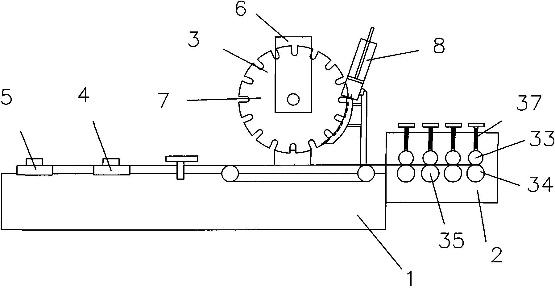
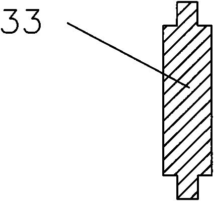
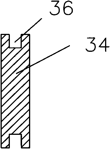
[0022] Such as figure 1 As shown, the strip brush machine described in this embodiment includes a body 1, a strip forming device 2, a hair feeding device 3, a shearing device 4 and a shearing device 5, a strip forming device 2, a hair feeding device 3, a shearing device 4 and a shearing device 5. The device 5 is arranged on the body 1 in turn, the hair feeding device 3 includes a frame 6, the frame 6 is provided with a circular hair feeding tray 7, and a hair storage device used in conjunction with the hair feeding tray 7 is provided beside the hair feeding tray 7 8. The slitting device 2 is formed by parallel arrangement of four groups of upper pressure rollers 33 and lower molding wheels 34 with a wheel-type slitting structure 35 arranged in parallel, as figure 2 As shown, the edge section of the upper pressure roller 33 can be in a "convex" shape, such as image 3 As shown, the edge of the lower mold wheel is provided with a groove 36 cooperating with the upper pressure r...
Embodiment 2
[0024] Such as Figure 4 As shown, the strip brush machine described in this embodiment, on the basis of Embodiment 1, the hair-feeding disc 7 mainly includes a disc body 9, and the edges of the disc body 9 are provided with fur-feeding grooves 10 at intervals. The top can be inclined, and a groove wall of the wool groove 10 forms a tip 11 with the edge of the disc body 9, and the other groove wall forms an arc 12 with the edge of the disc body 9, such as Figure 5 As shown, the disc body 9 becomes thinner from the center of the disc body 9 to the edge of the disc body 9, the center of the disc body 9 may be provided with a shaft hole 13, and the shaft hole 13 is provided with a shaft connection structure 14, and the shaft connection structure 14 is arranged in the shaft hole The keyway on 13, hair storage device 8 comprises hair box 15, is provided with depression bar 16 in the hair box 15, and hair box 15 is inclined setting, is provided with arc-shaped hair guide groove 17 ...
Embodiment 3
[0026] Such as image 3 As shown, in the strip brush machine described in this embodiment, on the basis of Embodiment 2, the shearing device 4 mainly includes a shearing knife 22, and the shearing knife 22 can be composed of two blades that are cut in planes on the left and right, one of which is a fixed blade 23, and the other One piece is a movable blade 24; the movable blade 24 is arranged in the blade moving channel 25, and the end of the movable blade 24 can be connected with a blade pushing arm 26, and the blade pushing arm 26 is hingedly connected with a connecting rod 27, and the connecting rod 27 is hingedly connected to the eccentric wheel 28, the eccentric wheel 28 is fixedly connected with the drive shaft 29, the drive shaft 29 is arranged on the drive wheel 30, the drive wheel 30 and the power wheel 32 are connected in transmission, and the power wheel 32 is connected to the motor. The shearing device 5 can mainly include a cutter 31 and a cylinder 47. The cutter 31...
PUM
 Abstract
Description
Claims
Application Information
 - R&D Engineer
- R&D Manager
- IP Professional
- Industry Leading Data Capabilities
- Powerful AI technology
- Patent DNA Extraction
Browse by: Latest US Patents, China's latest patents, Technical Efficacy Thesaurus, Application Domain, Technology Topic, Popular Technical Reports.
© 2024 PatSnap. All rights reserved.Legal|Privacy policy|Modern Slavery Act Transparency Statement|Sitemap|About US| Contact US: help@patsnap.com