
Automatic needle-turning and loop-transferring flat machine

A technology of automatic turning and knitting flat knitting machine, which is applied in the direction of flat knitting machine, knitting and weft knitting with separate action needles, which can solve the problems of a large number of manual operations, inability to receive flowers, and low efficiency, and achieve the effect of smooth running back and forth.

Inactive Publication Date: 2010-01-13
黄保华
View PDF0 Cites 11 Cited by
  • Summary
  • Abstract
  • Description
  • Claims
  • Application Information

AI Technical Summary

Problems solved by technology

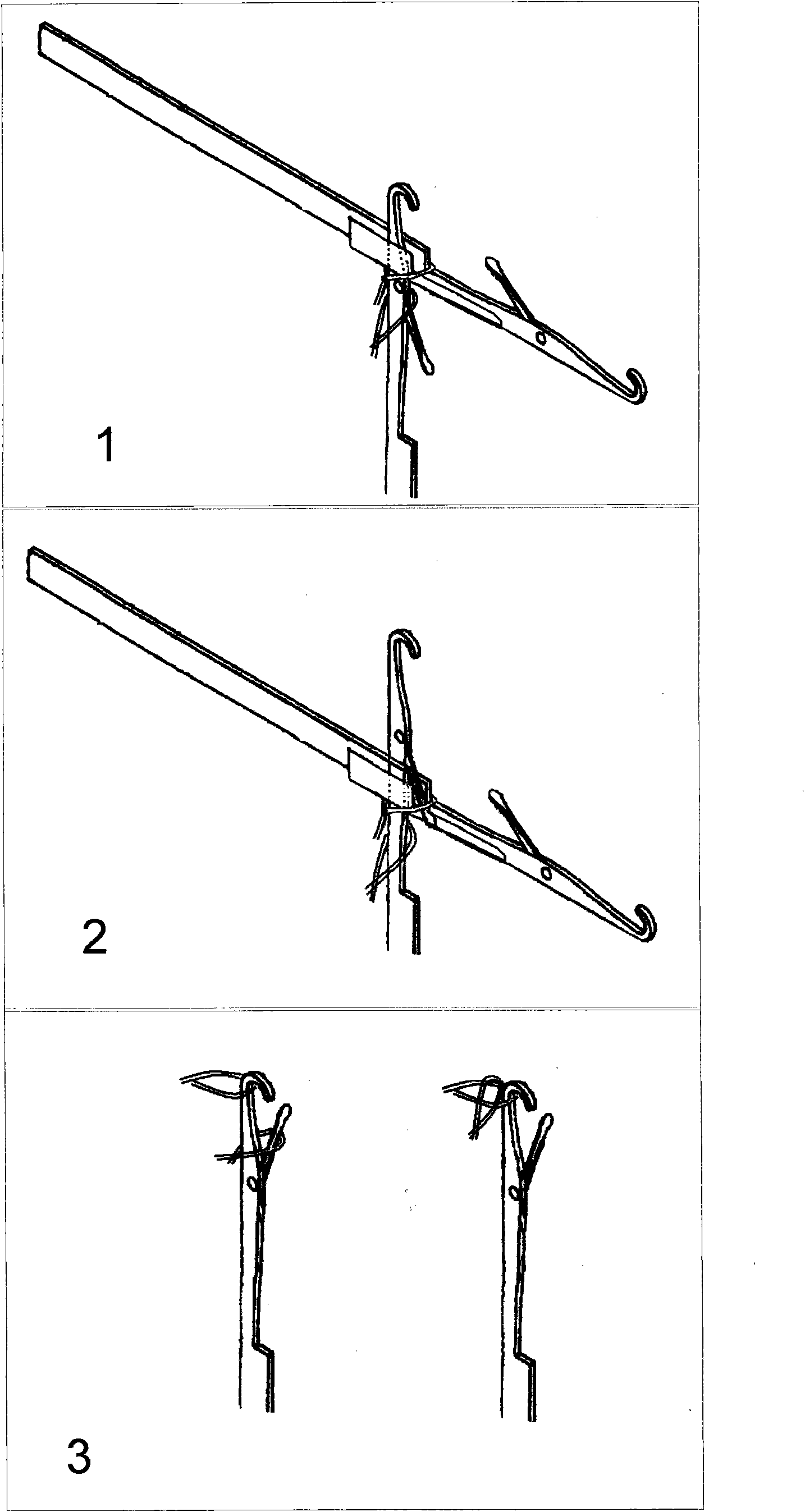
Pure hand-operated flat knitting machine: due to high labor intensity and low efficiency, there is a tendency to be eliminated; semi-automatic needle adding machine can only add needles and swing horizontally, requiring a lot of manual operation; automatic narrowing flat knitting machine: to a certain extent The labor intensity of the workers is reduced, but this model still cannot turn the needle back and forth, pick the hole, move the needle, separate the collar, etc., and can only do one-sided flower collection, but in fact it still needs a lot of manual operations, such as adjusting Density, needle opening, needle transfer, picking holes, twisting, moving needles, pocketing, side-separating and other actions, one operator of this model can only take care of 2 machines, the operator is actually very busy and hard ; And the existing market has a kind of knitting machine that can turn the needle, is to utilize a kind of knitting needle that has the transfer spring leaf that can transfer the loop, can realize the mutual transfer of the front and back, but can not receive flowers, can not add needles, close Collar, pick hole, etc.; fully automatic computerized flat knitting machine: this kind of flat knitting machine can solve all the above-mentioned functional deficiencies, but the structure is complicated, the price is expensive, and the cost is very high

Method used


Image

  • Automatic needle-turning and loop-transferring flat machine
  • Automatic needle-turning and loop-transferring flat machine
  • Automatic needle-turning and loop-transferring flat machine

Examples


Embodiment Construction

[0045] Example of yarn feeder control:

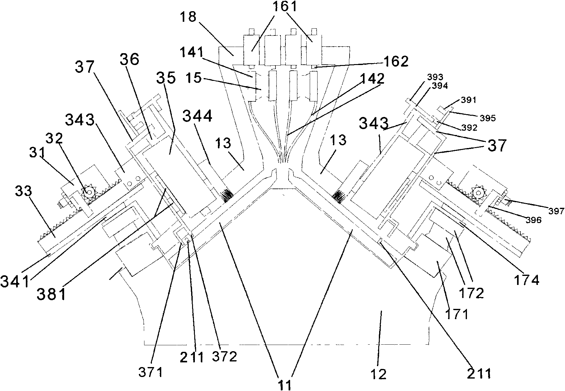
[0046] A plurality of electromagnets (161) are installed above the flyover (18) of the machine head, for controlling each yarn feeder (142), an electromagnet (161) is positioned in a yarn feeder (142) horse (141), and the electromagnet The iron core cover (162) of (161) stretches out, blocks the horse (141) on the yarn feeder (142), thereby makes the yarn feeder (142) random head movement, the iron core cover (162) of electromagnet (161) Retract, can not block the horse (141) of this yarn feeder (142), also can not drag this yarn feeder (142).

[0047] Installation example of machine head guide rail

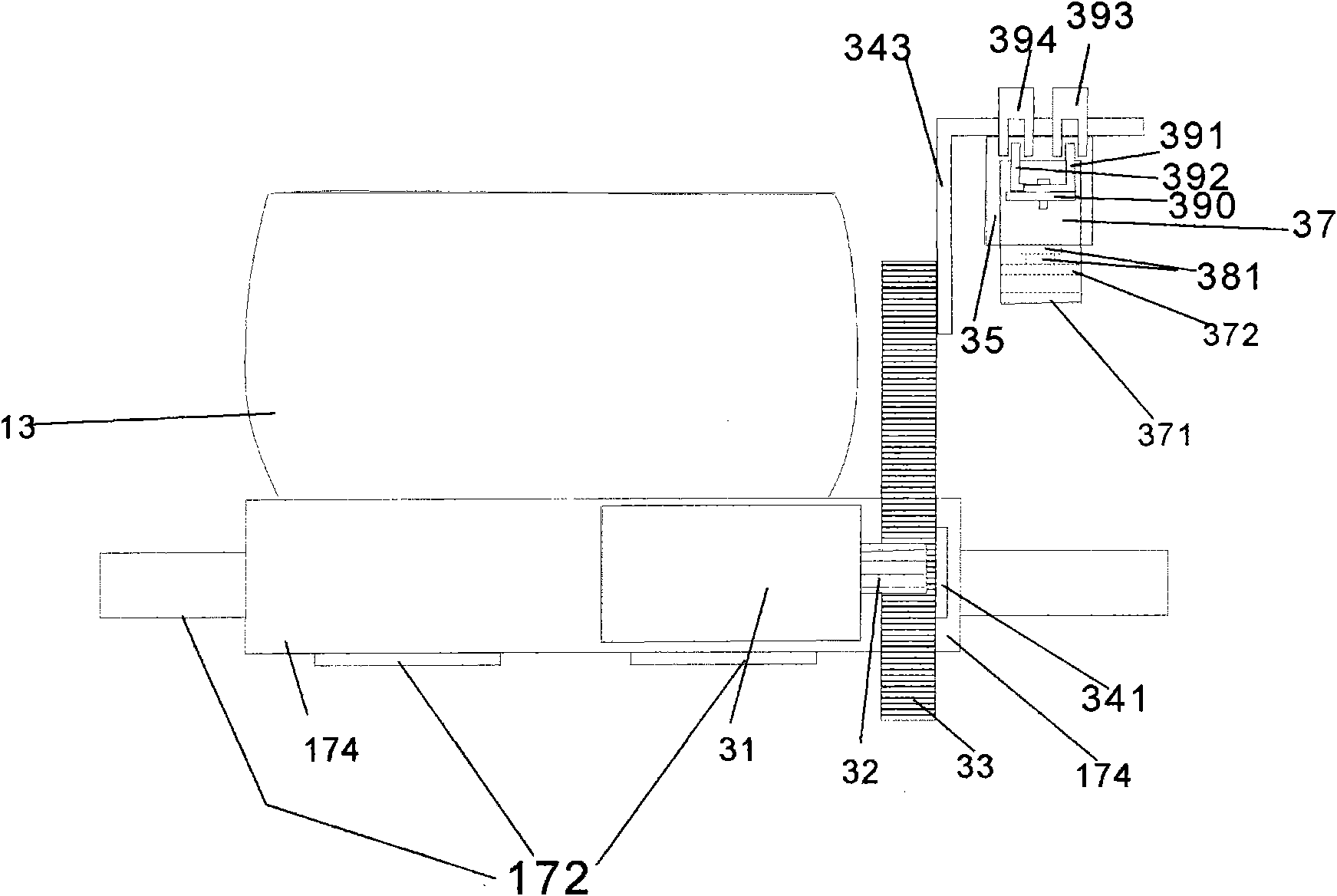
[0048]The front and back parts of the machine head (13) are all connected with the angle iron (174) of the machine head, and the angle iron (174) of the machine head is connected with the guide rail (172), and the guide rail (172) is fixed on the original guide bar (171) of the flat knitting machine, and the machine head and the movement ...


PUM


Abstract

The invention discloses an automatic needle-turning and loop-transferring flat machine with a spring leaf knitting needle and a machine head of an improved hand-operated flat machine, in particular a flat machine provided with two needle pushers on one side of the machine head and a needle pushing method of the needle pusher. Each needle pusher comprises an electric motor (31), a gear (32), a rack (33), a guide rail (341), an electromagnet frame (343), an electromagnet (35), an electromagnet iron core (36), an h-shaped cramp (37), a lower foot (371) of the cramp, an upper foot (372) of the cramp and a guide rail (381), wherein the rotation of the electric motor (31) of the needle pusher drives the h-shaped cramp (37) on the electromagnet (35) to push up and down; the h-shaped cramp (37) comprises the lower foot (371) of the cramp and the upper foot (372) of the cramp; and the precise rotation of the electric motor (31) of the needle pusher and the electromagnet (35) are controlled by a computer. The flat machine of the invention can automatically knit, push needles, and do various complicated loop transferring actions.

Description

Technical field [0001] This patent belongs to the field of a flat knitting machine, in particular to a flat knitting machine with automatic stitch transfer. Background technique [0002] At present, there are several types of needle flat knitting machines used by sweater factories. Pure hand-operated flat knitting machines: semi-automatic needle adding machines, automatic flower-receiving flat knitting machines, automatic turning knitting collar machines, fully automatic computerized flat knitting machines, these types of flat knitting machines Machines have many shortcomings. Pure hand-operated flat knitting machine: due to high labor intensity and low efficiency, there is a tendency to be eliminated; semi-automatic needle adding machine can only add needles and swing horizontally, requiring a lot of manual operation; automatic narrowing flat knitting machine: to a certain extent The labor intensity of the workers is reduced, but this model still cannot turn the needle bac...

Claims


Application Information

Patent Timeline
IPC IPC(8): D04B7/00D04B15/00D04B15/36D04B15/08D04B35/02D04B35/10
Inventor 黄保华
Owner 黄保华
Learn More