
Combined type support rack

A combined and knotted technology, used in display hangers, display shelves, display stands, etc., can solve the problems of slow assembly, troublesome use, weak positioning force, etc., and achieve the effect of rapid assembly

Inactive Publication Date: 2012-05-16
金学宏
View PDF5 Cites 0 Cited by
  • Summary
  • Abstract
  • Description
  • Claims
  • Application Information

AI Technical Summary

Problems solved by technology

[0004] However, because the positioning of the support frame is completed by using the bolt 62 to cooperate with the locking of the nut 63, it has the disadvantage of slow assembly, and when the size of the product is different, and the distance between the storage boards is to be adjusted, the bolt 62 needs to be adjusted. , The nut 63 can only be achieved by loosening and re-locking. Such a cumbersome action will cause troubles in use, and use rivets to overlap, and there are concerns about weak positioning force. Therefore, it is necessary to develop and innovate

Method used


Image

  • Combined type support rack
  • Combined type support rack
  • Combined type support rack

Examples


Embodiment Construction

[0035] In order to enable a further understanding and understanding of the purpose, features and effects of the present invention, please refer to the accompanying drawings for a detailed description below:

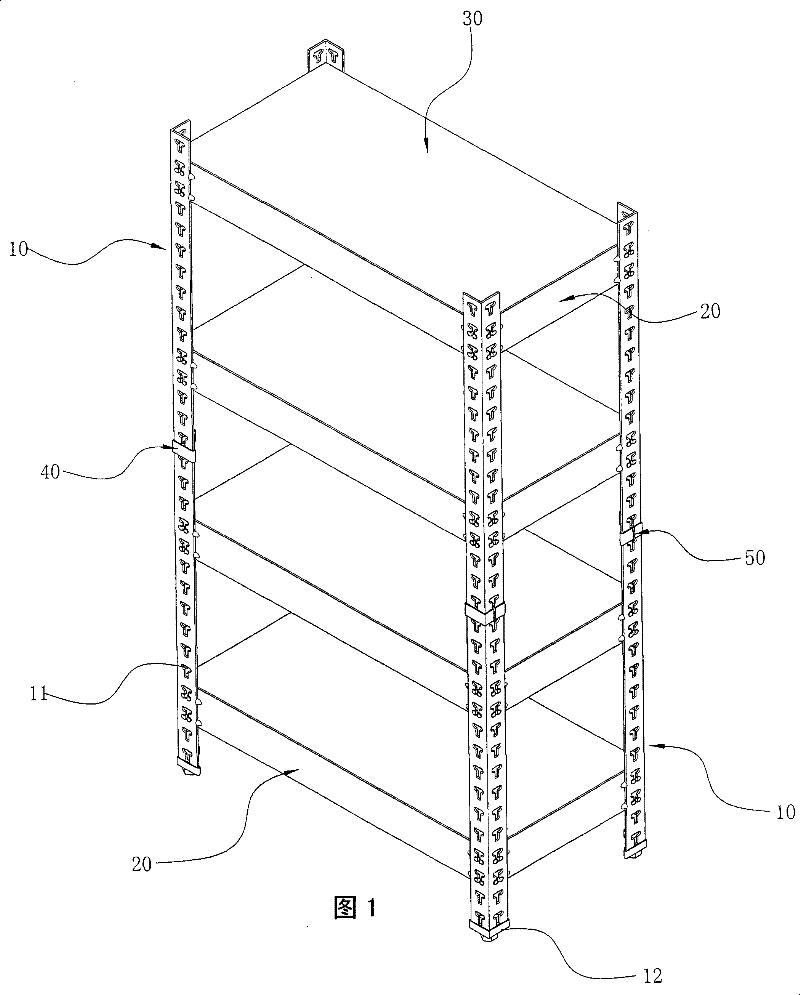
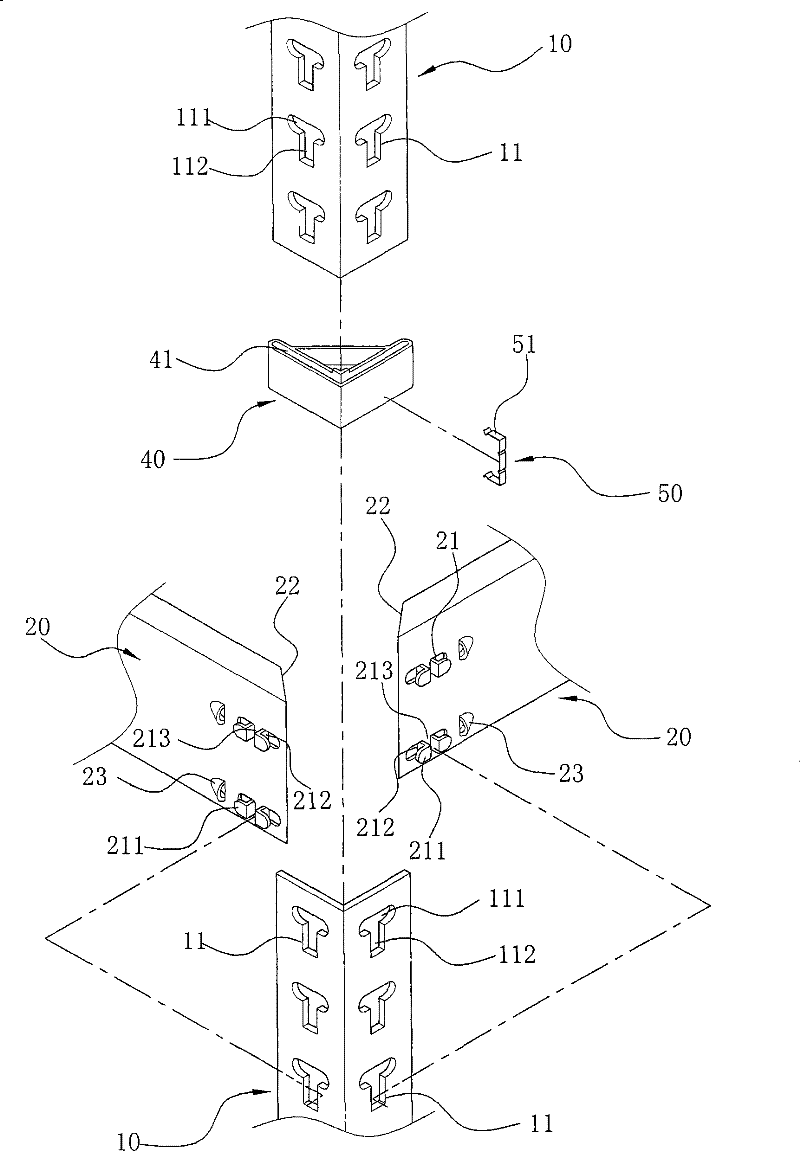
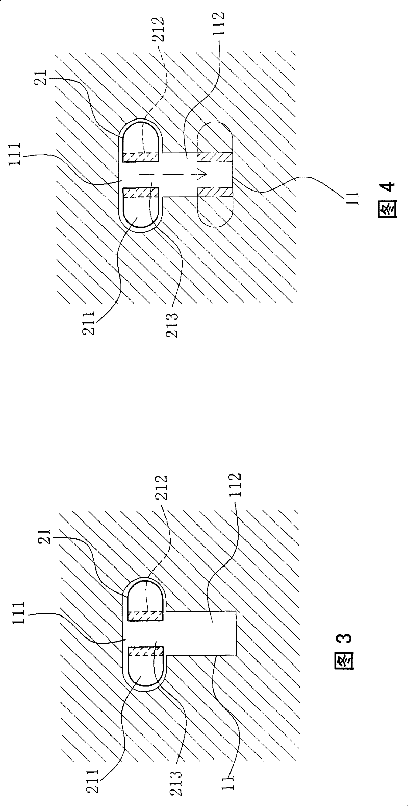
[0036] by the invention Figure 1 to Figure 6 As shown, the upright pole 10 and the supporting pole 20 are mainly embedded in the fastening hole 11 by using the protruding clamping block 21, and the storage board 30 is laid on it to complete the combination of the bearing frame.

[0037] Among them, first by figure 1 and figure 2 As shown, the fastening hole 11 is vertically pierced on the two-sided edge planes of the right-angled vertical rod 10, so that one side of the fastening hole 11 can become a larger penetration portion 111, and the other side becomes a smaller fastening portion 111. Knot 112, and because the vertical rod 10 needs to be supported against the ground, there is a liner 12 on its bottom end, and a height adjustment screw is combined on the liner 1...


PUM


Abstract

The invention relates to a combined type support rack. In the invention, an upright bar and a support bar are embedded into clamping and fixing holes mainly by utilizing projecting clamping junction blocks, and an object placement plate is laid so as to complete the combination of the support rack. The clamping and fixing holes are longitudinally penetrated and arranged on the two circumference planes of the upright bar in a right-angle shape, one side of each clamping and fixing hole can form a bigger penetration part, and the other side can form a smaller clamping junction part. Every two clamping junction blocks can form one group, the clamping junction blocks with the number of more than one group are longitudinally arranged on the outer surface of the support bar approaching to tangential edges of both sides at intervals and can be relatively matched with the clamping and fixing holes, the outer sides of the two clamping junction blocks in each group are both bent, and respectively extended out a stop piece along opposite direction, and flat and straight positions at the inner sides of the clamping junction blocks can relatively form one evasion part. As every two adjacent clamping junction blocks can form one group, an elastic space can be formed between the clamping junction blocks.

Description

technical field [0001] The invention relates to a "combined support frame" specially provided for placing various commodities and articles. The support frame is designed to be disassembled by DIY, and the disassembly operation is simple and the positioning force is also reliable. Background technique [0002] In order to fully display the products, so that consumers can browse all the products at a glance, and express product appeals more clearly, in order to stimulate consumers' desire to buy, most of the stores will use racks to display the products, and the types of products There are many kinds, with different sizes and heights, so when displaying, they will use the brackets that can adjust the height of the distance according to the needs. [0003] Such as Figure 7 and Figure 8 As shown, it is a commonly known and common support frame at present, which is formed by using a large number of angle irons 60 to lean against each other. These angle irons 60 are covered wit...

Claims


Application Information

Patent Timeline
Patent Type & Authority Patents(China)
IPC IPC(8): A47B47/00A47F5/00
Inventor 金学宏
Owner 金学宏
Learn More