
Handle device

A handle and installation technology, applied in the direction of wing fan handle, substation/distribution device casing, door/window accessories, etc., can solve problems such as cumbersome operations and achieve the effect of improving efficiency

Active Publication Date: 2010-01-06
TAKIGEN MFG CO LTD
View PDF1 Cites 9 Cited by
  • Summary
  • Abstract
  • Description
  • Claims
  • Application Information

AI Technical Summary

Problems solved by technology

[0003] However, in the conventional handle device, as described above, screws are used to attach the housing to the door panel, so it is necessary to insert the screws into the screw holes and fasten them, and there is a problem that the work is cumbersome.

Method used


Image

  • Handle device
  • Handle device
  • Handle device

Examples


Embodiment Construction

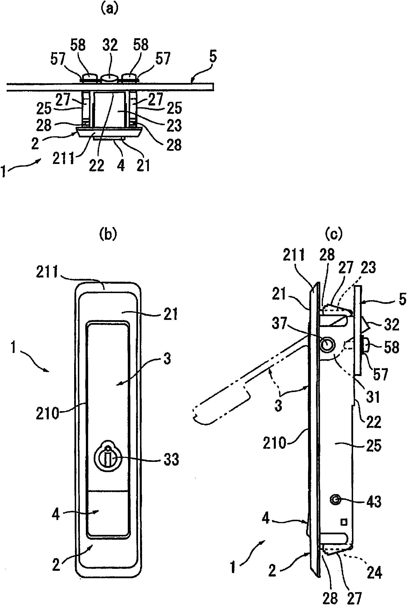
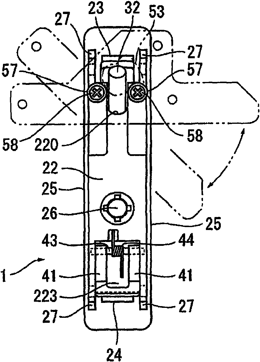
[0069] An embodiment of the present invention will be described below with reference to the accompanying drawings. Figure 1 to Figure 6 The handle device and its installation structure are shown. Such as figure 1 and figure 2As shown, the handle device 1 includes: a housing 2 fixed to the door panel, the front 21 of which has an opening 210, and a flange 211 on the outer periphery of the front 21; The handle 3; and the stopper 5 that is rotatably pivotally supported on the back side 22 of the housing 2 and is connected with the handle 3, and can be engaged and disengaged with the bracket on the side of the fixed frame such as the box body through the operation of the handle 3 , in this handle device 1, the handle 3 is protruded and rotated from the housing 2 toward a predetermined upright position by the operation of the button-type stopper 4 provided on the housing 2. Under the action of the handle 3, the back surface of the housing 2 The stopper 5 on the 22 side moves a...


PUM


Abstract

A handle device is capable of being mounted on a door board by one step, which improves the mounting operation efficiency greatly. A casing (2) is formed by forming engineering plastics having prescribed rigidity and spring, the circumference surface of the casing (2) is provided with a casing locking member (27) which extends to a prescribed position in an opening (60) for mounting from a back face side of the casing (2), and then extends toward a flange (211) side that is a prescribed position outside the opening (60) from said position in the opening (60), the casing locking member (27) is provided with a fixation part (28) on its front end, the marginal part of the opening (60) is clipped between the fixation part (28) and the flange (211) by inserting the casing (2) in the opening (60), and the casing (2) is fixed by a reaction of the casing locking member (27).

Description

technical field [0001] The present invention relates to a handle device used in equipment storage cabinets such as switchboards and control panels, and more particularly relates to mounting the handle on the shell fixed to the door panel in a undulating and rotatable manner, and protruding and rotating the handle toward a specified upright position or A handle device that disengages the stopper disposed on the back side of the housing and operatively linked with the handle from the bracket on the side of the fixed frame such as the box body by rotating the handle after the handle is protruded and rotated. Background technique [0002] In the past, when this kind of handle device was installed on the door panel, an opening for installing the housing of the handle device was formed on the door panel, and threaded holes or through holes were drilled in the vicinity of its two ends. Screw the small screw into the threaded hole of the door panel from the front side of the door pa...

Claims


Application Information

Patent Timeline
IPC IPC(8): E05B5/02H02B1/26H05K5/02
Inventor 濑川志朗
Owner TAKIGEN MFG CO LTD
Learn More