
Adjustable ventilation structure

An adjustable, venting technology, applied in the direction of instruments, electrical digital data processing, digital data processing components, etc., can solve the problems of reducing air intake, poor heat exchange effect, difficulty and high cost, avoiding repeated revisions Effect

Inactive Publication Date: 2009-12-30
INVENTEC CORP
View PDF0 Cites 29 Cited by
  • Summary
  • Abstract
  • Description
  • Claims
  • Application Information

AI Technical Summary

Problems solved by technology

[0007] The technical problem to be solved by the present invention is: in the prior art, the high-speed or low-speed operation of the cooling fan is only controlled by measuring the temperature without considering the temperature change, so the effective heat exchange purpose cannot be achieved, and a step will be generated to the power supply The power supply may be damaged due to the type of impact; and because the opening size of the other air inlets on the casing is also fixed, it cannot be adjusted in time to reduce the air intake, so the heat exchange effect of the system is not good; and the difficulty of design and high cost

Method used


Image

  • Adjustable ventilation structure
  • Adjustable ventilation structure
  • Adjustable ventilation structure

Examples


Embodiment Construction

[0024] The implementation of the present invention is described below through specific examples, and those skilled in the art can easily understand other advantages and effects of the present invention from the content disclosed in this specification. The present invention can also be implemented or applied through other different specific examples, and various modifications and changes can be made to the details in this specification based on different viewpoints and applications without departing from the spirit of the present invention.

[0025] Furthermore, the following drawings are all simplified schematic diagrams, and only illustrate the basic idea of ​​the present invention in a schematic manner, so only elements related to the present invention are shown in the drawings rather than drawn according to the number, shape and size of elements in actual implementation , the type, quantity and ratio of each component can be changed at will during its actual implementation, ...


PUM


Abstract

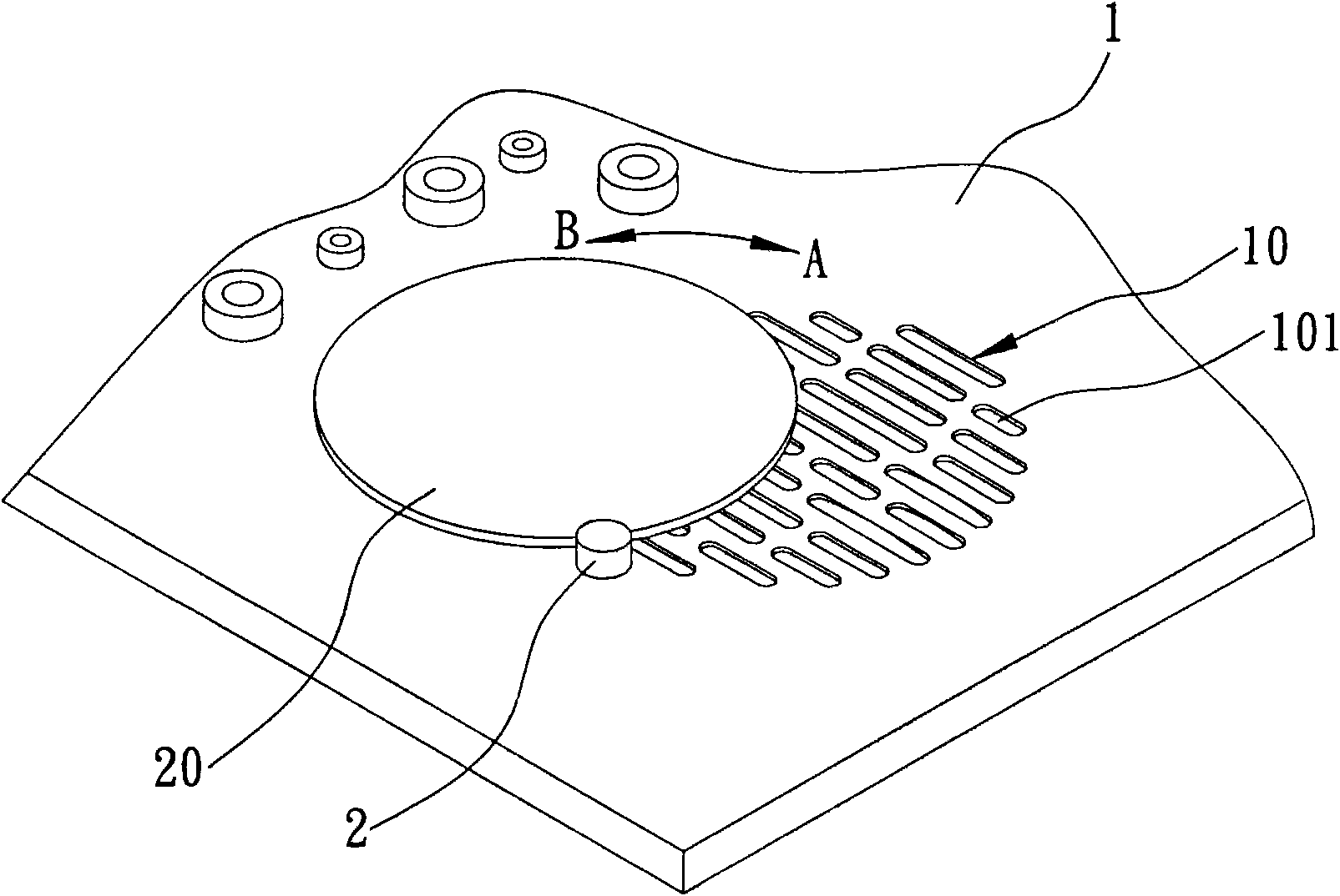
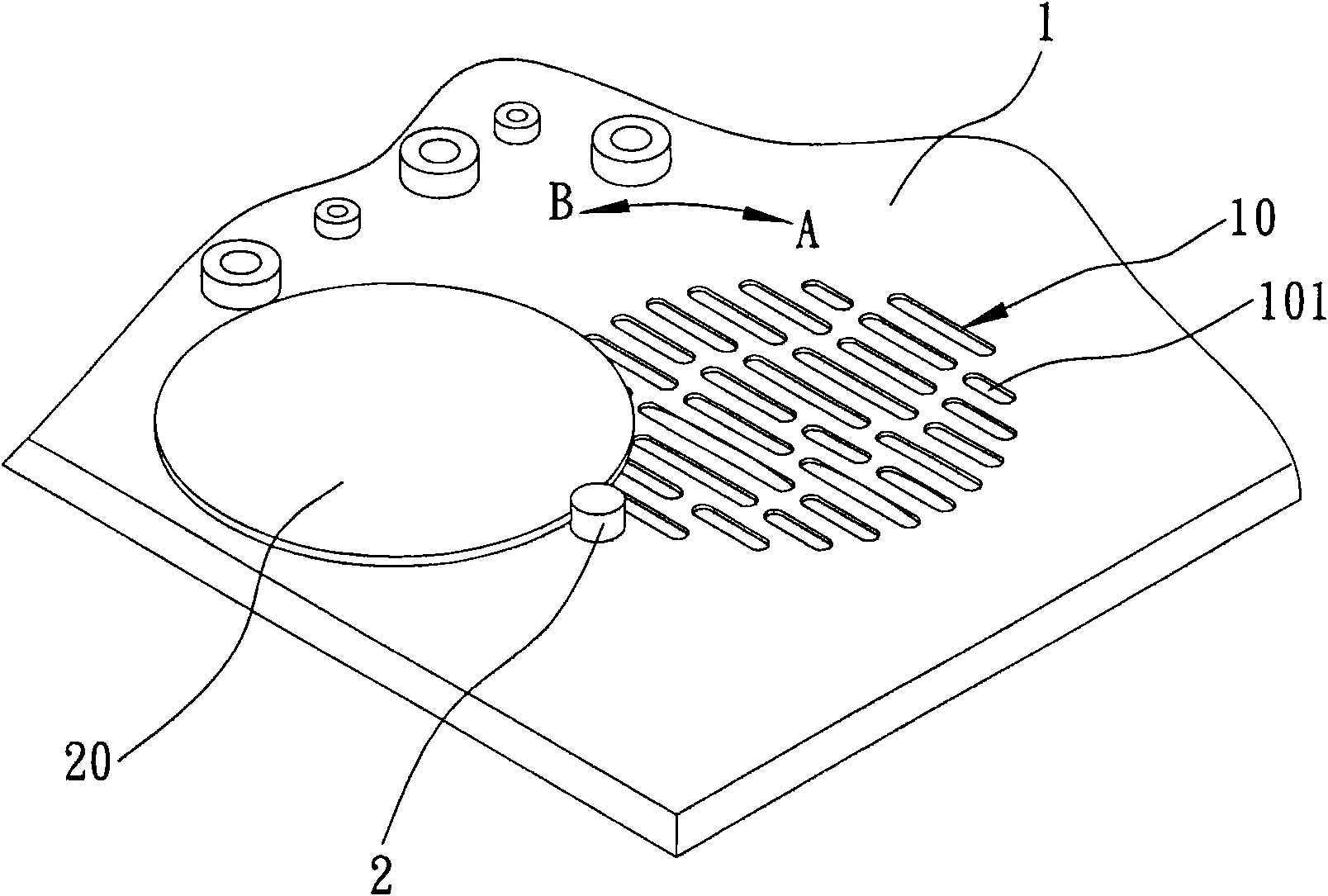
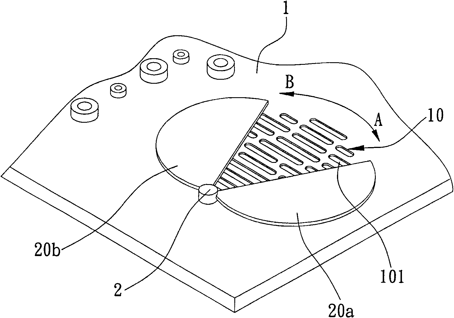
The invention relates to an adjustable ventilation structure applied in a notebook computer with a shell, the shell is provided with a ventilation opening and a driver positioned at one side of the ventilation opening, and the driver is connected with a baffle plate and used for driving the baffle plate to shade, or locally shade, or not to shade the ventilation opening, so as to adjust the opening area and the relative ventilation quantity of the ventilation opening.

Description

technical field [0001] The invention relates to a ventilation technology applied to a notebook computer, more specifically, to an adjustable ventilation structure applied to a notebook computer casing. Background technique [0002] With the high integration of large-scale integrated circuits in electronic device systems, the operating frequencies of central processing units (Central Processing Units, CPUs), hard disks and other components are getting higher and higher, and the heat generated by the entire system is also increasing. If the heat in the case of the electronic device cannot be dissipated in time, the accumulated heat will cause the components or components in the system to fail to work normally due to the rising temperature, and more seriously, it is very likely to cause the components or components to malfunction or be damaged . In order to ensure the normal operation of the electronic device system, the means of heat exchange must be adopted, that is, the coo...

Claims


Application Information

Patent Timeline
IPC IPC(8): G06F1/20
Inventor 姚志信萧丰能
Owner INVENTEC CORP
Learn More