
Dominant wave automatic frequency tracking numerical receiver

A digital receiver and automatic tracking technology, applied in radio wave measurement systems, instruments, etc., can solve problems such as reducing system reliability, increasing system equipment, and limiting system performance.

Inactive Publication Date: 2009-12-30
杭州敏探科技有限公司
View PDF5 Cites 5 Cited by
  • Summary
  • Abstract
  • Description
  • Claims
  • Application Information

AI Technical Summary

Problems solved by technology

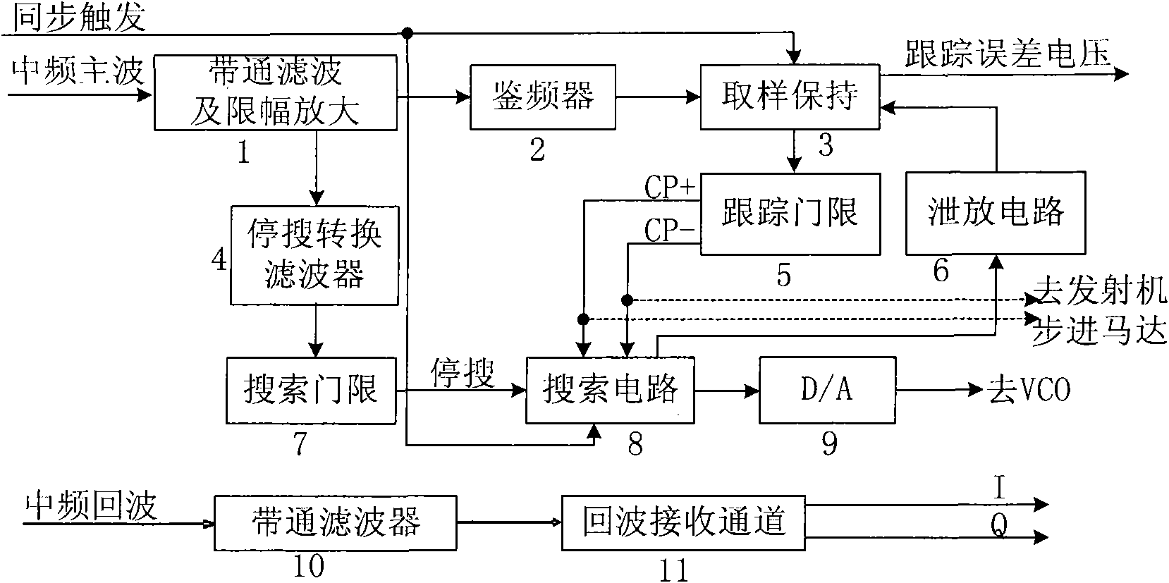
[0007] In addition to the receiving channel, the existing scheme also uses a separate self-frequency tuning loop. The front end needs an external frequency adjustable component (VCO or frequency adjustable transmitting tube), and the analog mode is used to control the VCO frequency or the mechanical mode to control the transmitter transmission frequency. The system The performance is limited, which increases the amount of equipment in the system. At the same time, because most of them are analog devices, the reliability of the system is reduced.

Method used


Image

  • Dominant wave automatic frequency tracking numerical receiver
  • Dominant wave automatic frequency tracking numerical receiver
  • Dominant wave automatic frequency tracking numerical receiver

Examples


Embodiment Construction

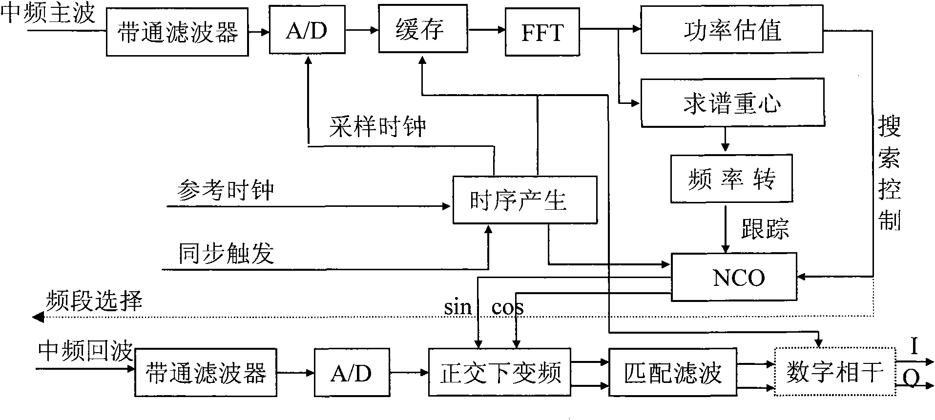
[0012] The present invention will be further described below in conjunction with the accompanying drawings. The receiver combines main wave digital frequency tracking and digital intermediate frequency reception into one, and the system realization includes two parts: main wave processing and echo processing.

[0013] Step 1: The input of the main wave receiving channel adopts a broadband band-pass filter (10), and the bandwidth meets the frequency variation range required by the system. Like the general S-band radar, the frequency drift range of the magnetron is generally within ±8MHz, so the receiving channel bandwidth of the system is 16M, and the AD sampling is greater than 32M. For the millimeter-wave radar with large drift, its drift bandwidth may be as high as hundreds of megabytes. In addition to the need to select a higher-speed AD converter, at the same time, a segmented tracking method can be used to divide the entire frequency range into multiple segments. Through ...


PUM


Abstract

The invention provides a dominant wave (DW) automatic frequency tracking numerical receiver. The numerical receiver not only has the function of radar numerical intermediate-frequency (IF) receiving, but also realizes numerical automatic frequency tracking and locking received by radar, and the system does not need traditional automatic frequency control loop circuits and external frequency adjustment components. The technical scheme of the invention is as follows: the IF DW and the IF echo wave channels of the receiver are received by wideband, the receiving bandwidth is determined according to the frequency coverage really needed by a radar system. The invention is mainly characterized in that the receiver carries out wideband sampling and buffers DW data received from the radar, the DW power spectrum is obtained by real-time numerical FFT transformation, the center of gravity of unilateral band spectrum is calculated, the frequency estimation of DW is obtained by the value of the center of gravity of spectrum and is converted into corresponding numerical control oscillator (NCO) frequency control word, the frequency control word obtained by calculation is used to control the frequency of NCO under synchronous trigger to realize automatic tracking of the DW frequency of NCO, AD sampling is carried out on the radar echo signal and then orthogonal down-conversion is carried out on the radar echo signal and the numerical frequency signal generated by NCO, the echo wave video IQ signal is obtained after IF matched filtering, and frequency adjustable components are only NCO. When DW frequency is calculated, the DW power is simultaneously calculated to judge whether the current DW input is valid or not, and if the DW is invalid, the search of system frequency is started. A timing sequence generating circuit generates AD sampling clock, generates DW sampling control sequence and data latching sequence according to trigger signals, and provides NCO clock.

Description

technical field [0001] The invention relates to a main wave automatic frequency tracking digital receiver, which is a receiver which uses real-time digital frequency spectrum analysis to realize the main wave frequency tracking, and belongs to the field of radar receiving and signal processing. Background technique [0002] The superheterodyne radar receiver converts the high-frequency signal into an intermediate frequency signal for amplification and filtering. The frequency of general IF amplifiers and filters is relatively fixed, and this IF frequency is called the rated IF frequency. In actual work, the frequencies of the magnetron transmitter and the local oscillator of the receiver are not coherent, and the transmission frequency of the magnetron transmitter will change with the change of the power supply voltage, ambient temperature, output load, etc. Its frequency drift range is different according to the radar operating band, generally between several megabytes and...

Claims


Application Information

Patent Timeline
Patent Type & Authority Applications(China)
IPC IPC(8): G01S7/285
Inventor 王金础
Owner 杭州敏探科技有限公司
Learn More