
Multifunctional timing chain wheel cover

A timing sprocket, multi-functional technology, applied in the direction of engine components, machines/engines, casings, etc., can solve problems such as valve phase angle deviation, damage to valve train parts, timing chain system failure, etc., to prevent The effect of jumping teeth

Active Publication Date: 2009-12-30
安庆福莱克斯动力科技有限公司
View PDF0 Cites 5 Cited by
  • Summary
  • Abstract
  • Description
  • Claims
  • Application Information

AI Technical Summary

Problems solved by technology

[0003] During the operation of the engine, the timing chain system will skip teeth due to wear of the timing chain and sprocket, excessive fluctuations in the tension of the timing chain system, and cold start, which will change the phase angle of the valve train, resulting in The performance of the engine is reduced, and even the parts of the valve train are damaged
[0004] The timing chain will have a certain amount of elongation after being used for a period of time. After the chain is elongated, the transmission accuracy of the phase will be affected, resulting in a deviation of the gas distribution phase angle.
For an engine with adjustable valve timing, when there is a deviation in the valve timing, it is necessary to remove the valve chamber cover and timing sprocket cover (some engines also need to remove the oil pan) to adjust the phase; To do experiments on the stand, the engine needs to be removed from the stand to adjust the phase, which is difficult to disassemble and takes a long time, which increases the cost
[0005] As an important part of the timing chain system, the hydraulic tensioner is especially important for its working performance and the lubrication of the timing chain. However, due to the metallic nature of the timing chain cover material, it is impossible to directly observe the hydraulic tensioner. This has also become a huge hidden danger for the failure of the timing chain system

Method used


Image

  • Multifunctional timing chain wheel cover
  • Multifunctional timing chain wheel cover
  • Multifunctional timing chain wheel cover

Examples


Embodiment Construction

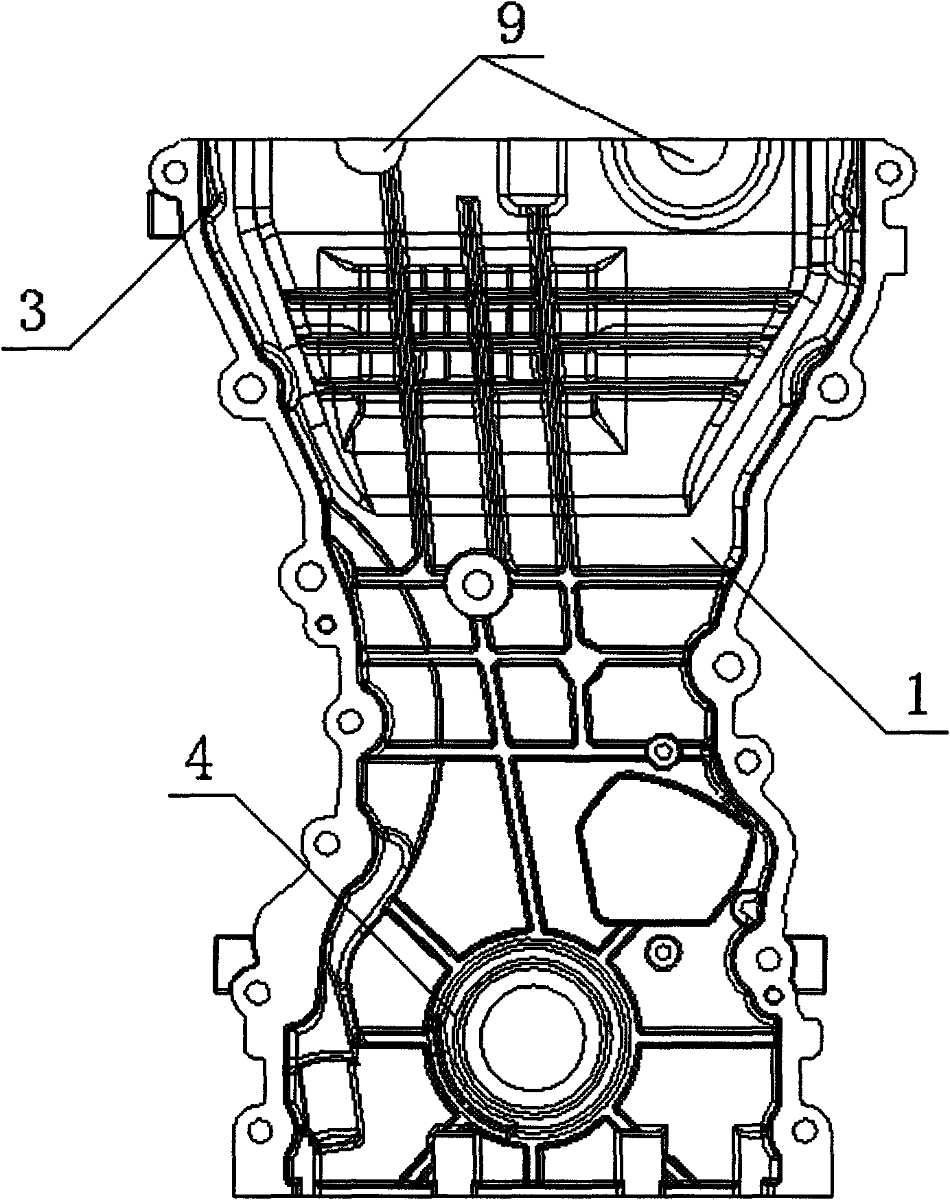
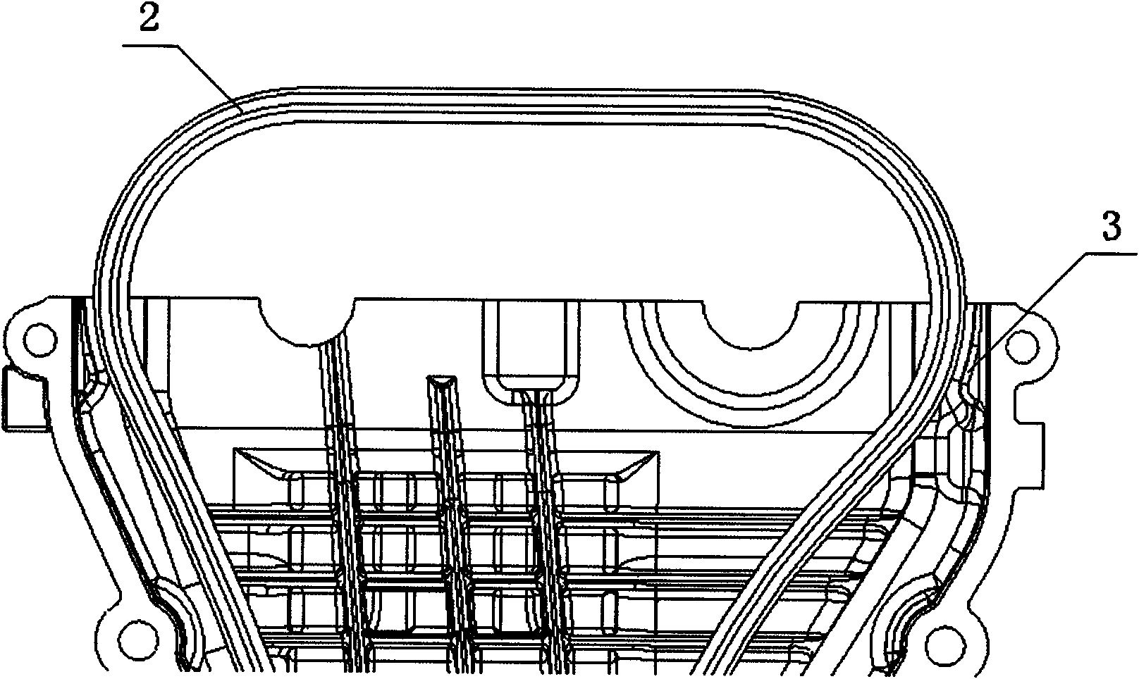
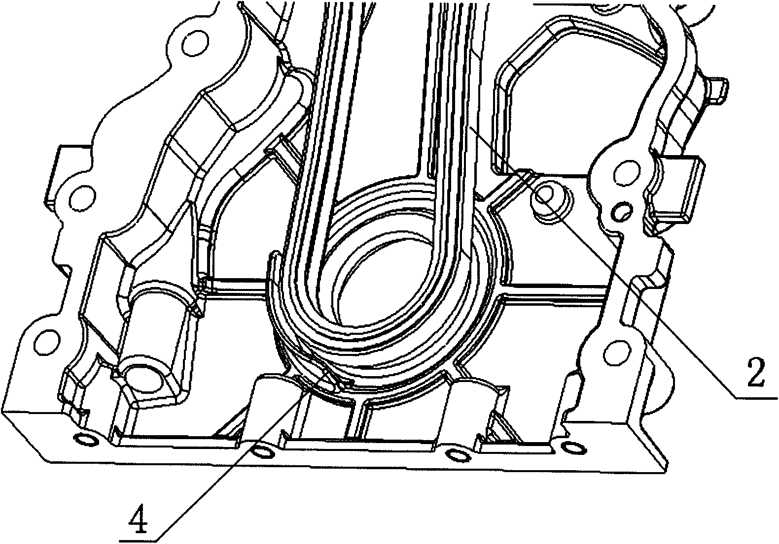
[0028] Depend on Figure 1-Figure 7 Combining the shown structures, it can be seen that the multi-functional timing sprocket cover includes a timing sprocket cover 1, and the inner side of the timing sprocket cover 1 is located at the inner side of the timing chain 2 and the sprocket on the exhaust side of the camshaft. The first chain guide groove 3 is provided at the place where the meshing and the camshaft intake side sprocket are about to separate, and the second chain guide groove 4 is provided at the timing chain 2 and the crankshaft sprocket; The top of the cover 1 is provided with grooves 9 corresponding to the bolts of the intake camshaft and the bolts of the exhaust camshaft, and the semicircular rubber plug 8 is correspondingly installed in the groove 9; the timing sprocket cover 1 includes Two parts, namely the metal part and the transparent visible part 7 corresponding to the hydraulic tensioner 5, the visible part 7 is transparent high-strength plexiglass, the vi...


PUM


Abstract

The invention discloses a multifunctional timing chain wheel cover, comprising a timing chain wheel cover and characterized in that: a first chain guide groove is respectively arranged on a position to be meshed between a timing chain inside the timing chain wheel cover and a steam exhaust side chain wheel of a camshaft and a position of a steam admission side chain wheel of the camshaft to be separated, and a second chain guide groove is arranged on the timing chain and a crankshaft chain wheel; grooves are arranged at the top of the timing chain wheel cover corresponding to a steam admission camshaft bolt and a steam exhaust camshaft bolt, and a semicircle gel block is correspondingly arranged in the groove; and the timing chain wheel cover comprises two parts: a metal part and a transparent visual part corresponding to a hydraulic tensioner. The structure helps prevent a timing chain system from jumping over teeth in virtue of the chain guide groove arranged on the timing chain cover, simplify a work process of the engine for adjusting phases in virtue of the arranged removable semicircle gel block and facilitate directly observing work condition of the hydraulic tensioner in virtue of an arranged visual part.

Description

technical field [0001] The invention relates to an engine timing system, in particular to a multifunctional timing sprocket cover. Background technique [0002] Engine timing chain system is of great significance in transmitting crankshaft torque and ensuring valve timing accuracy and reliability. The timing sprocket cover seals the timing chain system while also dampening noise. [0003] During the operation of the engine, the timing chain system will skip teeth due to wear of the timing chain and sprocket, excessive fluctuations in the tension of the timing chain system, and cold start, which will change the phase angle of the valve train, resulting in The performance of the engine is reduced, and even the parts of the valve train are damaged. [0004] The timing chain will have a certain amount of elongation after being used for a period of time, and the elongation of the chain will affect the transmission accuracy of the phase, resulting in a deviation of the gas distr...

Claims


Application Information

Patent Timeline
IPC IPC(8): F01L1/348F02F7/00
Inventor 孟莉莉马自立
Owner 安庆福莱克斯动力科技有限公司
Learn More