
Fuel gas generator

A kind of technology of gas generator and combustion system

Inactive Publication Date: 2011-01-19
刘洪斌
View PDF0 Cites 0 Cited by
  • Summary
  • Abstract
  • Description
  • Claims
  • Application Information

AI Technical Summary

Problems solved by technology

[0002] At present, the problems of the commonly used gas generators are: (1) the hot air outlet pressure is low, the flow rate is small, and the temperature and flow adjustment range is narrow; (2) a single fan is used, which wastes electric energy and the fan is easily damaged; (3) the burner Incomplete combustion, low combustion efficiency

Method used

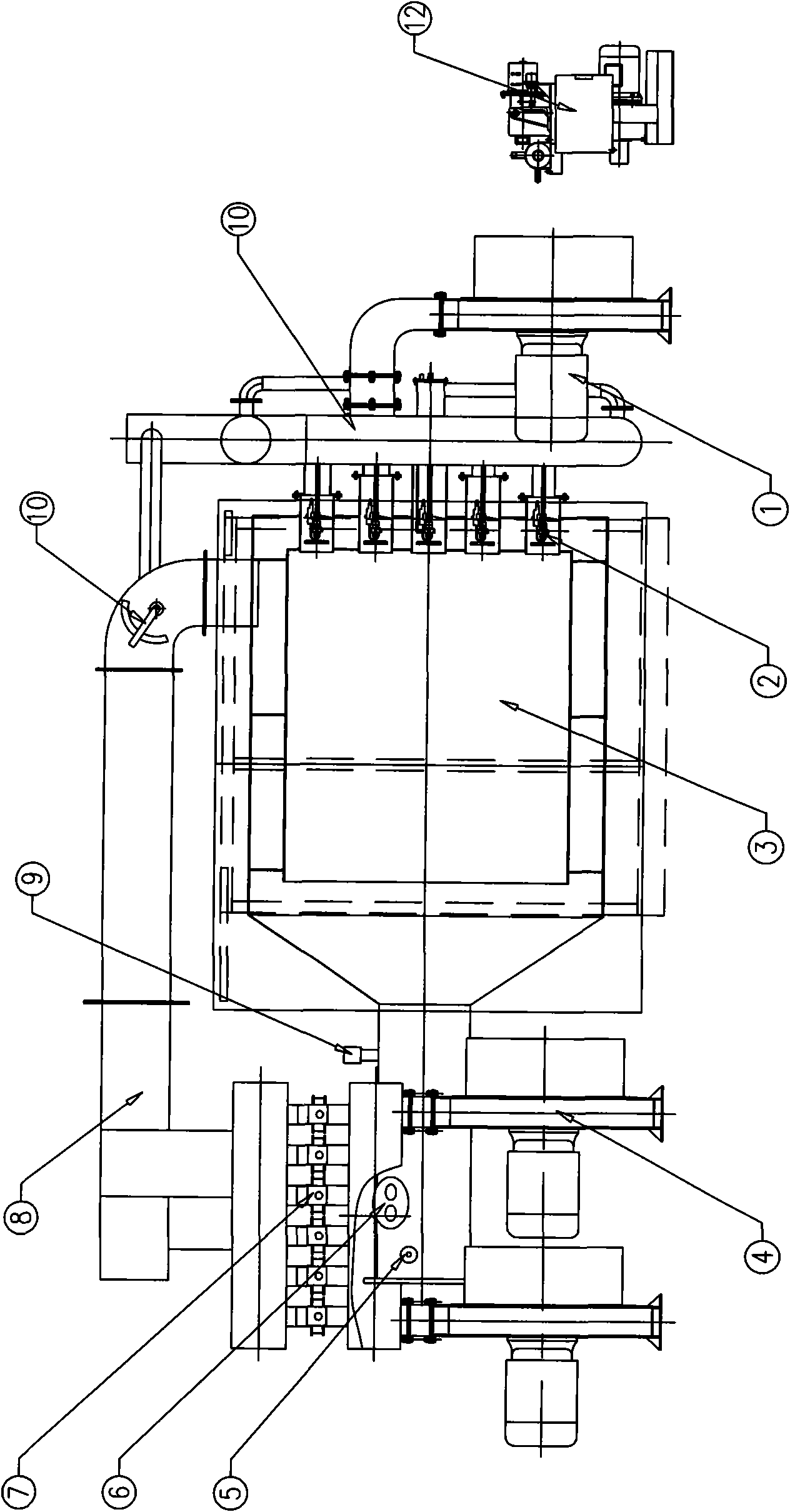
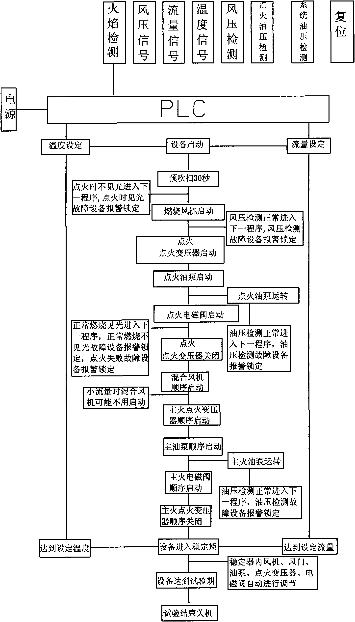

Image

  • Fuel gas generator
  • Fuel gas generator

Examples


Embodiment Construction

[0012] figure 1 Among them, the gas generator is composed of gas generator body 3, air supply system, combustion system, detection system, PLC control system, oil supply system and balanced air adjustment system; the air supply system is composed of combustion fan 1 and mixing fan 4 , the combustion fan 1 is connected to the gas generator body 3 through a pipeline, and the mixing fan 4 is connected to the air duct 8 of the gas generator body 3 through an electric butterfly valve 7; the combustion system is composed of a combustion spray gun 2, and the combustion spray gun 2 is installed in the gas generator On the side wall of the gas generator body 3; the detection system is composed of a flow meter 6, a pressure sensor 5 and a thermocouple 9, and the flow meter 6, the pressure sensor 5 and the thermocouple 9 are installed in the air duct 8 of the gas generator body, and the flow meter 6. The pressure sensor 5 and the thermocouple 9 are respectively connected to the PLC contr...


PUM


Abstract

The invention discloses a device capable of generating high-temperature high-pressure smoke gas, in particular to a fuel gas generator which can muffle under test states, save energies and have high burning efficiency. The technical proposal is as follows: the fuel gas generator is characterized by consisting of a fuel gas generator body, an air supply system, a burning system, a detecting system, a PLC control system, an oil supply system, and a balancing air adjusting system, wherein the air supply system consists of a burning fan and a mixed fan; the burning system consists of a burning blow gun; the burning blow gun is arranged on the side wall of the fuel gas generator body; the detecting system consists of a flowmeter, a pressure sensor and a thermoelectric couple; the flowmeter, the pressure sensor and the thermoelectric couple are respectively connected with the PLC control system; the PLC control system receives a signal transmitted from the detecting system and implements control on the air supply system and the burning system; the air supply system consists of an oil supply pump set; the oil supply pump set is connected with the oil path of the fuel gas generator body; and the balancing air adjusting system consists of a balancing air valve.

Description

technical field [0001] The invention belongs to the field of gas generator noise reduction devices, in particular to a gas generator capable of providing specific temperature, flow rate and pressure and realizing noise reduction, energy saving and high combustion efficiency under test conditions. Background technique [0002] At present, the problems of commonly used gas generators are: (1) the hot air outlet pressure is low, the flow rate is small, and the temperature and flow adjustment range is narrow; (2) the use of a single fan wastes electric energy, and the fan is easily damaged; (3) the burner Incomplete combustion and low combustion efficiency. Contents of the invention [0003] The object of the present invention is to provide a test device for flow regulation, pressure regulation, and accurate detection accuracy on the noise reduction test bench, and can provide specific temperature, flow, pressure and realize noise reduction and energy saving in the test state....

Claims


Application Information

Patent Timeline
Patent Type & Authority Patents(China)
IPC IPC(8): G01M99/00G05B19/05
Inventor 刘洪斌
Owner 刘洪斌
Learn More