
Trace oil igniting coal dust firing device for multiple oil guns

A technology of pulverized coal combustion and small amount of oil, applied in the direction of burner, combustion ignition, combustion method, etc., can solve the problems of large distance, no staggered setting of main oil gun and auxiliary oil gun on the opposite side, ignition failure, etc.

Inactive Publication Date: 2010-12-08
HARBIN INST OF TECH
View PDF2 Cites 0 Cited by
  • Summary
  • Abstract
  • Description
  • Claims
  • Application Information

AI Technical Summary

Problems solved by technology

[0003] The present invention solves the problem that the existing combustion device has a relatively large distance between the main oil gun and the auxiliary oil gun on the same side, and the main oil gun and the auxiliary oil gun on the opposite side are not arranged in a staggered manner, so that ignition failure is prone to occur; A pulverized coal combustion device with multiple oil guns and micro-oil volume ignition

Method used


Image

  • Trace oil igniting coal dust firing device for multiple oil guns
  • Trace oil igniting coal dust firing device for multiple oil guns
  • Trace oil igniting coal dust firing device for multiple oil guns

Examples


specific Embodiment approach 1

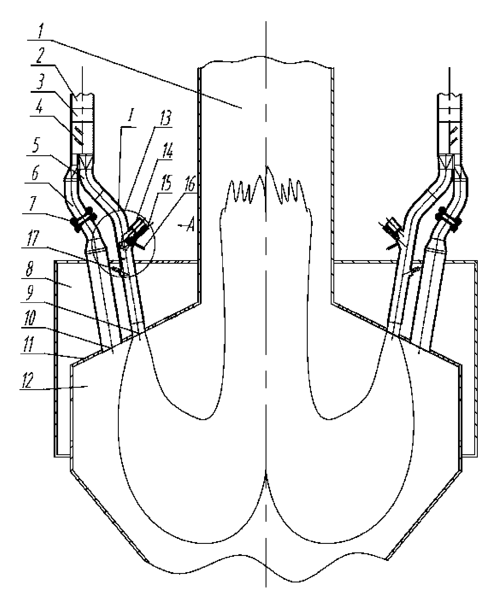
[0010] Specific implementation mode one: combine Figure 1~3 , Figure 4a~4b Describe this embodiment mode, a kind of pulverized coal combustion device described in this embodiment mode includes a primary air duct 2, a grid divider 3, a pulverized coal thick-lean separator 4, and two pipelines for dense pulverized coal 5. Light coal powder pipeline 6, light coal powder pipeline baffle plate 7, fire inspection piece 16, two main oil guns 14, two auxiliary oil guns 15 on the same side and two auxiliary oil guns 17 on the opposite side; the grille The inlet end of the equalizer 3 is connected to one end of the primary air duct 2, and the coal dust separator 4 is arranged inside the grid equalizer 3, and the outlet end of the grid equalizer 3 is respectively connected to two dense coal dust pipelines 5 The inlet end of the light pulverized coal pipeline 6 is connected, and the outlet ends of the two thick pulverized coal pipelines 5 and the outlet ends of the light pulverized coa...

specific Embodiment approach 2

[0013] Specific implementation mode two: combination Figure 1~3 , Figure 4a~4b Describe this embodiment, the distance between the intersection of the centerline of the main oil gun 14 and the centerline of the auxiliary oil gun 15 on the same side and the centerline of the thick pulverized coal pipeline 5 in this embodiment is L is 90-95mm. Other components and connections are the same as those in the first embodiment.

specific Embodiment approach 3

[0014] Specific implementation mode three: combination figure 1 with image 3 Describe this embodiment, the distance M between the centerline of the main oil gun 14 and the centerline of the auxiliary oil gun 17 on the opposite side and the centerline of the thick pulverized coal pipeline 5 in this embodiment is 600-650mm. Other compositions and connections are the same as those in Embodiment 1 or 2.


PUM


Abstract

The invention provides a trace oil igniting coal dust firing device for multiple oil guns, relates to a firing device, and solves the problem of easily failed ignition due to the fact that distance between a main oil gun and an auxiliary oil gun on the same side is large, and the main oil gun and an auxiliary oil gun on the opposite side are not alternately arranged in the prior firing device. The main oil gun and the auxiliary oil gun on the opposite side are alternately and oppositely arranged on side walls of a concentrated coal dust pipeline; distances of crossing points among the centralline of the main oil gun, the central line of the auxiliary oil gun on the same side and the central line of the concentrated coal dust pipeline are between 80 and 100mm; and distances of the crossing points of the central line of the main oil gun, the central line of the auxiliary oil gun on the opposite side and the central line of the concentrated coal dust pipeline are between 500 and 700mm. The distance between the main oil gun and the auxiliary oil gun on the same side is close so as to ensure that fuel which is sprayed from the auxiliary oil gun and has excellent atomization can be directly sprayed into high temperature flame generated by ignition of the main oil gun for fierce firing, and the flame generated after fuel sprayed from the main oil gun and the auxiliary oil gun is fired can support each other to form whole flame which has large length and roughness and good rigidity and can ignite high concentrated coal dust.

Description

technical field [0001] The invention relates to a combustion device, in particular to a pulverized coal combustion device with multiple oil guns and micro-oil volume ignition applied to a W-shaped flame boiler. Background technique [0002] Large-scale power plant boilers consume a lot of oil during ignition and low-load stable combustion. In order to save fuel, power generation companies shift the focus of fuel saving from low-load stable combustion to boiler ignition and shutdown (oil consumption accounts for 60% when power plant boilers start and stop. , low-load stable fuel consumption accounts for 40%). Therefore, the research on micro-oil ignition combustion technology is of great significance to the development of my country's electric power industry and the entire national economy. The Chinese patent application number is ZL200720170025.1 utility model patent. This design arranges the main oil gun and auxiliary oil gun in sequence along one side of the burner. The ...

Claims


Application Information

Patent Timeline
Patent Type & Authority Patents(China)
IPC IPC(8): F23D1/00F23Q9/00
Inventor 李争起刘春龙陈智超赵洋胡志勇
Owner HARBIN INST OF TECH
Learn More