
Circle quick door-opening device of pressure container

A door-opening device and pressure vessel technology, applied to pressure vessels, fixed-capacity gas storage tanks, mechanical equipment, etc., can solve the problems of complex fast-opening cover fixing structure and easy wear and tear of sealing rings, and achieve less fixed structure requirements and lower manufacturing costs Reduced effect

Inactive Publication Date: 2009-12-02
余姚市舜江机械实业有限公司
View PDF0 Cites 12 Cited by
  • Summary
  • Abstract
  • Description
  • Claims
  • Application Information

AI Technical Summary

Problems solved by technology

[0002] Existing pressure vessels, such as vulcanization tanks, shaping tanks, sterilizing pots, autoclaves, etc., whether they are horizontal or vertical, basically include a tank body and a quick-opening cover arranged at the port of the tank body. The quick-opening cover includes a sealing The upper flange and the upper flange welded to the end of the head. There are teeth on the lower flange evenly distributed in the circumferential direction of the flange. The teeth of the upper flange and the teeth of the lower flange are overlapped and locked. Opening, this kind of staggered teeth opening and closing structure requires relative rotation between the upper flange and the lower flange during the process of opening and closing the cover, which has the following disadvantages: First, the sealing ring is easily worn by the friction of the upper flange; Considering both lifting and turning, the fixing structure of the quick-opening cover is relatively complicated

Method used


Image

  • Circle quick door-opening device of pressure container
  • Circle quick door-opening device of pressure container
  • Circle quick door-opening device of pressure container

Examples


Embodiment Construction

[0021] The present invention will be further described in detail below in conjunction with the accompanying drawings and embodiments.

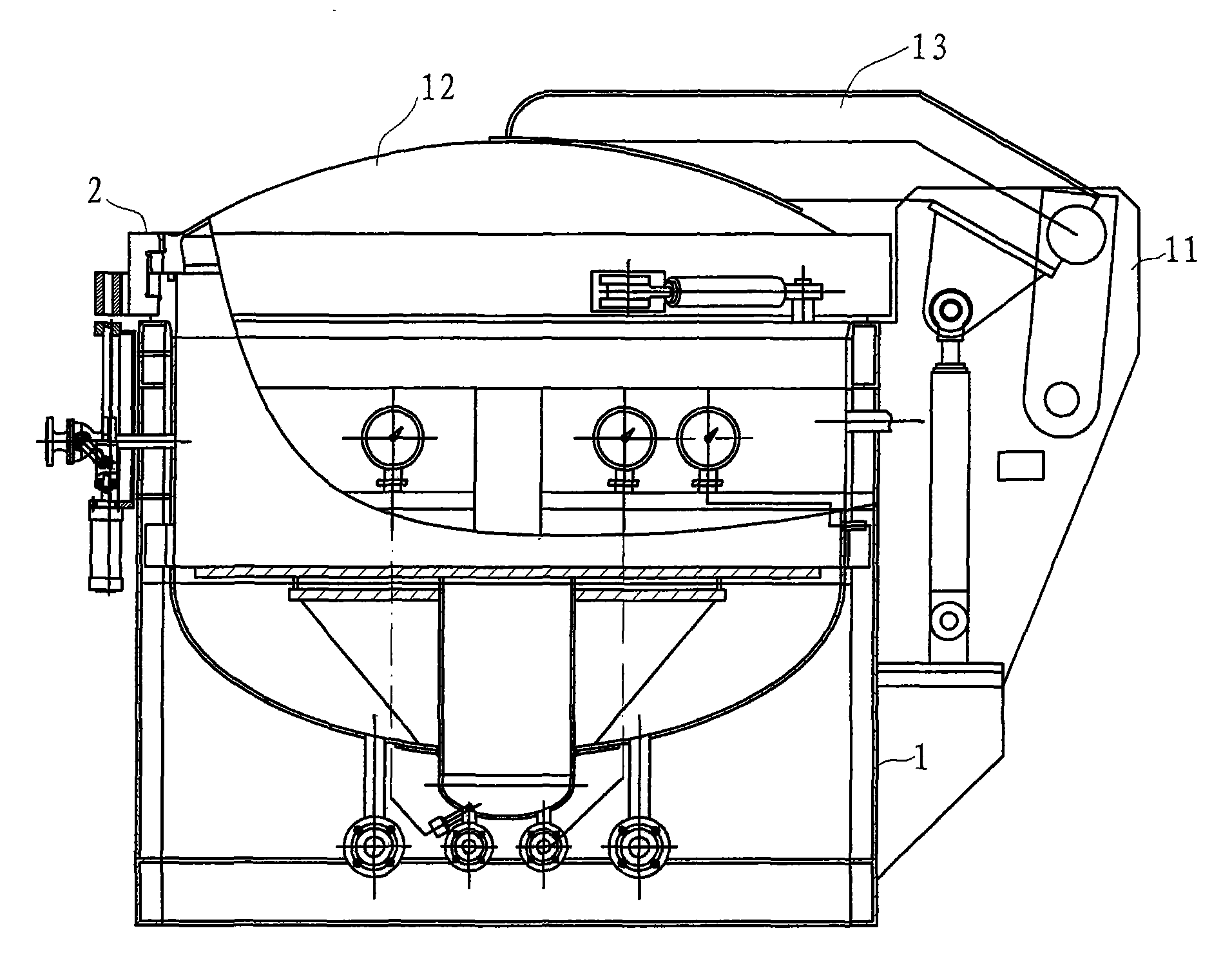
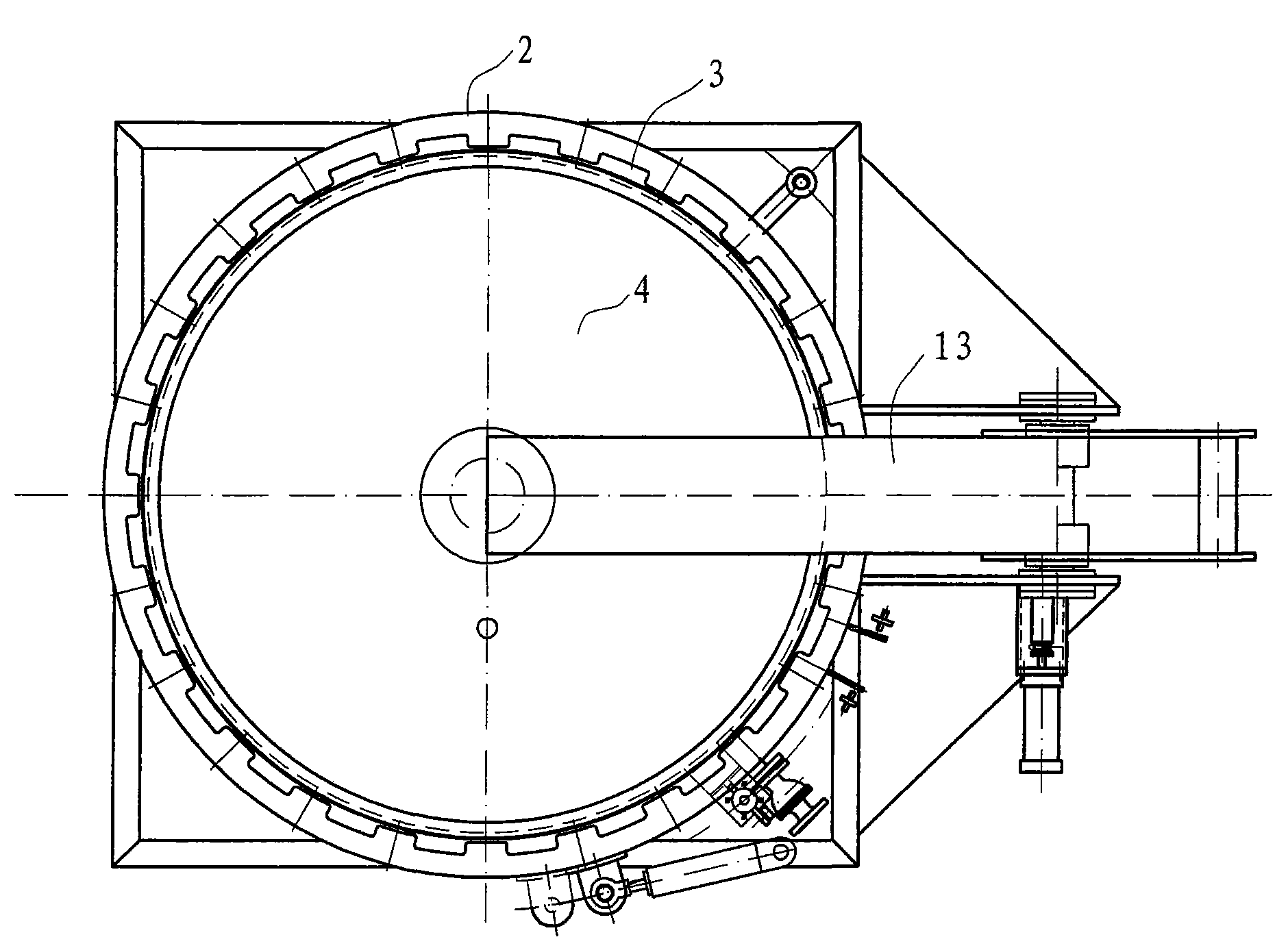
[0022] Such as Figure 1 to Figure 7 As shown, the pressure vessel in this embodiment is a vulcanization tank, including a tank body 1, a head 4, a rocker arm 13, a rotating ring 2, an upper flange 3, and a lower flange 5, and the upper flange 3 is located at the bottom of the head 4. The port forms a quick-opening cover 12, which is fixed on one end of the rocker arm 13 and can be lifted up and down, while the other end of the rocker arm 13 is rotatably set on the side 11 of the tank body, and the lower flange 5 is connected to the tank body 1 port.

[0023] The upper flange 3 is evenly distributed with upper flange teeth 31 along the circumferential direction, and the lower flange 5 is evenly distributed with lower flange teeth 51 along the circumferential direction. For the cover 12 and the tank body 1, the upper end of the rotating ring ...


PUM


Abstract

The invention discloses a circle quick door-opening device of a pressure container, which comprises an end enclosure, an upper flange and a lower flange which is connected with a tank body. The upper flange is arranged at a port of the end enclosure, the upper flange is evenly distributed with upper flange teeth along the circumferential direction, and the lower flange is evenly distributed with lower flange teeth along the circumferential direction. The device is characterized in that the device also comprises a circle which is arranged at the circumferential outsides of the upper flange and the lower flange, the upper end part of the circle is provided with upper teeth matched with the upper flange teeth to be locked, and the lower end part of the circle is provided with lower teeth matched with the lower flange teeth to be locked. Compared with the prior art, the device has the advantages that the locking and loosing of the circle are adopted for replacing the rotation of a quick opening cover, then relative rotation is not needed between the upper flange and the lower flange, and a sealing ring is abraded little; in addition, only the rising and falling of the quick opening cover are considered, the rotation factor does not need to be considered, so the requirement for the fixed structure of the quick opening cover is relatively less, and the manufacturing cost can be reduced.

Description

technical field [0001] The invention relates to a pressure vessel, in particular to a rotating and quick door opening device for the pressure vessel, which can be applied to pressure vessels such as vulcanization tanks, shaping tanks, sterilizing pots, and autoclaves. Background technique [0002] Existing pressure vessels, such as vulcanization tanks, shaping tanks, sterilizing pots, autoclaves, etc., whether they are horizontal or vertical, basically include a tank body and a quick-opening cover arranged at the port of the tank body. The quick-opening cover includes a sealing The upper flange and the upper flange welded to the end of the head. There are teeth on the lower flange evenly distributed in the circumferential direction of the flange. The teeth of the upper flange and the teeth of the lower flange are overlapped and locked. Opening, this kind of staggered teeth opening and closing structure requires relative rotation between the upper flange and the lower flange...

Claims


Application Information

Patent Timeline
Patent Type & Authority Applications(China)
IPC IPC(8): F16J13/24
Inventor 蒋春雷
Owner 余姚市舜江机械实业有限公司
Learn More