
Garbage can

A trash can and fixed frame technology, applied in the field of trash cans, can solve problems such as laborious and labor-intensive, and achieve the effect of labor-free and easy operation

Inactive Publication Date: 2009-12-02
谈发来
View PDF0 Cites 0 Cited by
  • Summary
  • Abstract
  • Description
  • Claims
  • Application Information

AI Technical Summary

Problems solved by technology

But when taking out the garbage, lifting the long hook needs to bear the gravity of the garbage at the bottom, so it takes a lot of effort

Method used


Image

  • Garbage can

Examples


Embodiment Construction

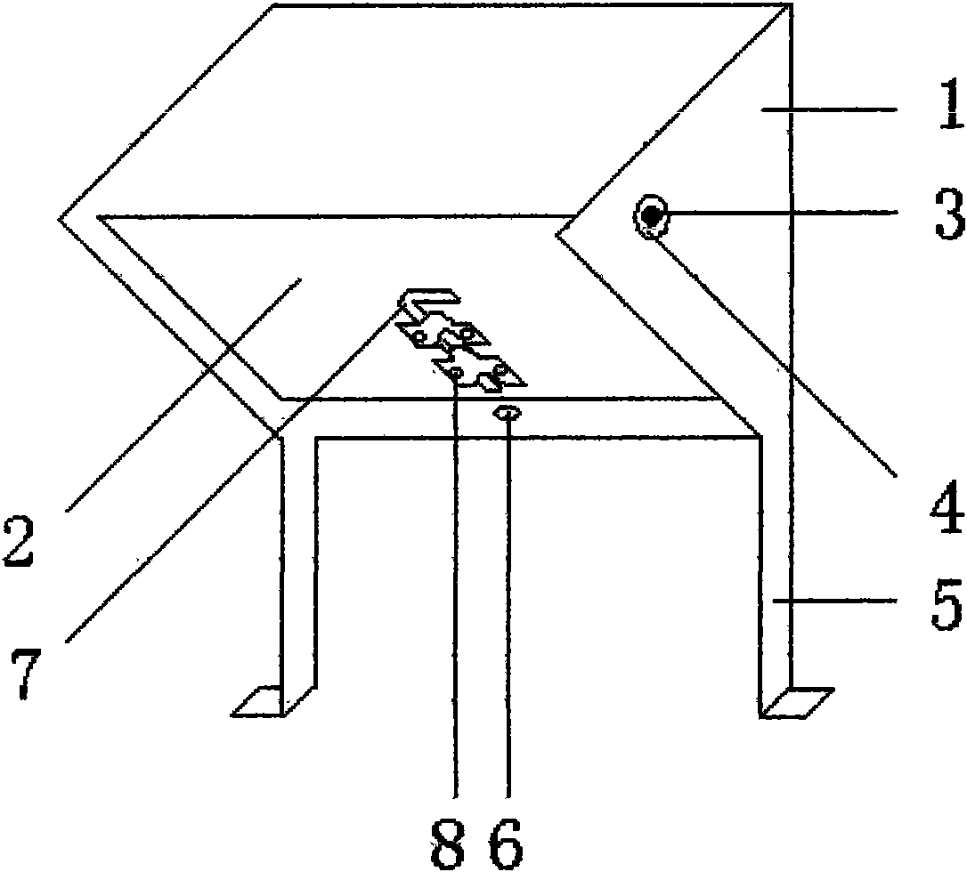
[0008] like figure 1 As shown, a trash can includes a fixed frame 1 and a movable piece 2, and the fixed frame 1 and the movable piece 2 are connected as a whole through a rotating shaft 3. The fixed frame 1 and the movable sheet 2 are made of cast iron. The upper end of the fixed frame 1 is provided with a shaft hole 4 . Both sides of the fixed frame 1 are provided with brackets 5 . The fixed frame 1 is fixedly connected with the bracket 5 . The lower end of the fixed frame 1 is provided with a socket 6 . The upper end of the movable piece 2 is provided with a rotating shaft 3 . The lower end of the movable piece 2 is provided with a latch 7 . Latch 7 is fixed on the lower end of movable piece 2 by screw 8. The rotating shaft 3 is embedded in the shaft hole 4 . When collecting rubbish, the latch 7 of the lower end of the movable piece 2 is inserted in the jack 6 of the fixed frame 1 lower end, and the fixed frame 1 and the movable piece 2 lower ends are combined togeth...


PUM


Abstract

The invention discloses a garbage can and aims to provide the garbage can which saves labor in the process of dumping garbage. The invention adopts the technical proposal that the garbage can provided with a fixed frame and a movable plate is manufactured. The garbage can disclosed by the invention comprises the fixed frame and the movable plate which are connected into a whole through a rotation axis. The technical proposal adopted by the invention is simple and convenient to operate, and the garbage can saves the labor of loading the garbage into a garbage truck.

Description

technical field [0001] The present invention relates to trash cans. Background technique [0002] The description of the application number 032173695 discloses a trash can. The technical scheme of the utility model is: it includes a bucket body, the bottom surface of the bucket and the bucket body are movably connected by a connecting device, and a long hook is installed on the bottom surface. The length of the long hook is Equivalent to the height of the barrel. When the bottom surface is closed with the barrel body, the long hook can be hooked to the edge of the barrel. The beneficial effects of the utility model are as follows: when loading garbage, hang the long hook on the edge of the bucket; when taking out the garbage, take off the long hook, the bottom surface will automatically open, and the garbage can be poured out without inverting the bucket body. But when taking out the garbage, lifting the long hook needs to bear the gravity of the garbage at the bottom, so ...

Claims


Application Information

Patent Timeline
Patent Type & Authority Applications(China)
IPC IPC(8): B65F1/00B65F1/12B65F1/14
Inventor 谈发来
Owner 谈发来
Learn More