
Method for operating a printing press

A printing machine and working mode technology, applied to printing machines, general parts of printing machinery, rotary printing machines, etc., can solve problems such as reducing printing quality

Active Publication Date: 2012-05-23
HEIDELBERGER DRUCKMASCHINEN AG
View PDF7 Cites 0 Cited by
  • Summary
  • Abstract
  • Description
  • Claims
  • Application Information

AI Technical Summary

Problems solved by technology

This difference causes torsional vibrations, which are transmitted from the ink distribution roller to the following rollers and cylinders and reduce the printing quality

Method used


Image

  • Method for operating a printing press
  • Method for operating a printing press
  • Method for operating a printing press

Examples


Embodiment Construction

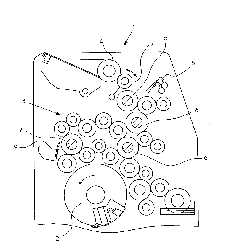
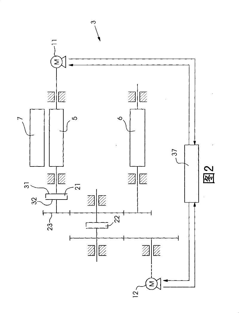
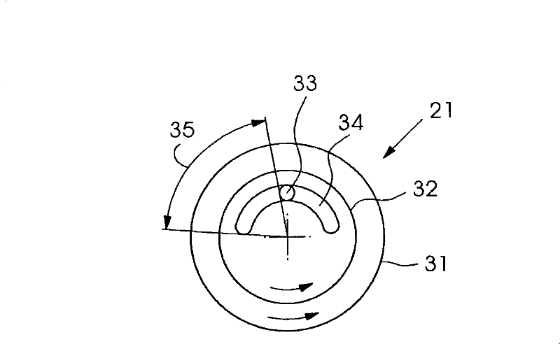
[0021] figure 1 A printing press 1 for printing sheets is shown in detail. The detail shows a printing unit for offset printing. The printing unit comprises an impression cylinder and a blanket cylinder, which are not shown in the figures. Furthermore, the printing unit comprises a printing form cylinder 2 , a dampening unit (not shown in detail) for wetting the printing form cylinder 2 and an inking unit 3 for inking the printing form cylinder 2 . The inking unit 3 is a roller inking unit and comprises an ink fountain with a fountain roller 4 , a first roller 5 , second rollers 6 and further rollers not shown in detail, including transfer rollers and ink form rollers. The second rollers 6 are rotationally driven by gears which are arranged concentrically with the second rollers 6 and are connected in a rotationally fixed manner. These gears are a transmission 23 (see figure 2 )made of. In addition, the inking unit 3 includes an inking roller 7 , which pivots back and fo...


PUM


Abstract

The present invention relates to a method for operating a printing machine in a print operating mode and another operating mode, for example a maintenance mode. In the print operating mode, bringing a vibrating roller periodically into contact with a first roller (5) of an inking unit (3), driving the first roller (5) rotationally by a first motor (11), driving a second roller (6) of the inking unit (3) rotationally by a second motor (12), transmitting no torque from the first motor (11) to the second roller (6) through a clutch (21) therebetween, and activating the first motor (11) by a control device (37) causing the first roller (5) to rotate at a rotational speed in a constant ratio to a rotational speed of the second roller (6). In the other operating mode, driving the first and second rollers (5, 6) rotationally by the first motor (11) and transmitting torque from the first motor (11) to the second roller (6) through the clutch (21).

Description

technical field [0001] The invention relates to a method for operating a printing press in a printing mode and in another mode, in particular a maintenance mode. Background technique [0002] The exchange of printing plates and the cleaning of the inking unit are part of the maintenance of printing presses that is carried out between printing jobs. In order to shorten the maintenance, efforts were made to carry out plate changing and inking unit washing at the same time. In order to allow this simultaneous operation, the plate cylinder is driven by the main motor of the printing press and the inking unit is driven by a separate motor. A printing press with the motor required for this is described in EP 1167026 B1. [0003] A long known problem in printing presses is the transfer roller impact problem. The reason for this impact of the transfer roller is the difference in peripheral speed that exists between the two rollers during the impact of the transfer roller against ...

Claims


Application Information

Patent Timeline
Patent Type & Authority Patents(China)
IPC IPC(8): B41F31/00B41F13/008B41F31/14B41F31/15B41F33/10
CPCB41F31/004
Inventor U·卢克哈特O·诺瓦拉W·施图茨
Owner HEIDELBERGER DRUCKMASCHINEN AG
Learn More