
Combine harvester

A technology for combine harvesters and harvesting devices, which is applied in the direction of harvesters, cutters, agricultural machinery and implements, etc., and can solve the problem of uneven left and right directions of dust discharge layers, inconsistent growth states of seedlings, and uneven plowing of rice straw chips. Uniformity and other problems, to achieve the effect of reducing the increase of threshing load or poor sorting, reducing rice straw scraps, and good efficiency

Active Publication Date: 2011-06-15
ISEKI & CO LTD
View PDF0 Cites 0 Cited by
  • Summary
  • Abstract
  • Description
  • Claims
  • Application Information

AI Technical Summary

Problems solved by technology

Therefore, there is a problem that the number of sorted objects on the shaking sorting shelf increases, and the grains are discharged to the outside of the threshing device together with the rice straw chips in a state where the sorting cannot be performed sufficiently, resulting in a harvest loss.
[0006] In addition, in order to solve this problem, in the case of adopting a structure in which the dust discharged from the dust discharge treatment chamber is directly discharged outside the machine, the dust will fall on the rice straw on the adjacent uncut land side, and the When harvesting the row of rice straws on the uncut land side, the rice straws are harvested together with dust, which causes troubles such as an increase in the threshing load and poor sorting.
[0007] In addition, the layer of dust discharged from the dust removal treatment room and accumulated on the farmland surface is uneven in the left and right directions, the plowing amount of rice straw chips in the next cultivation operation is uneven, and the growth state of the transplanted seedlings is inconsistent. The problem

Method used


Image

  • Combine harvester
  • Combine harvester
  • Combine harvester

Examples


Embodiment Construction

[0029] Hereinafter, one embodiment for implementing the present invention will be specifically described based on the drawings.

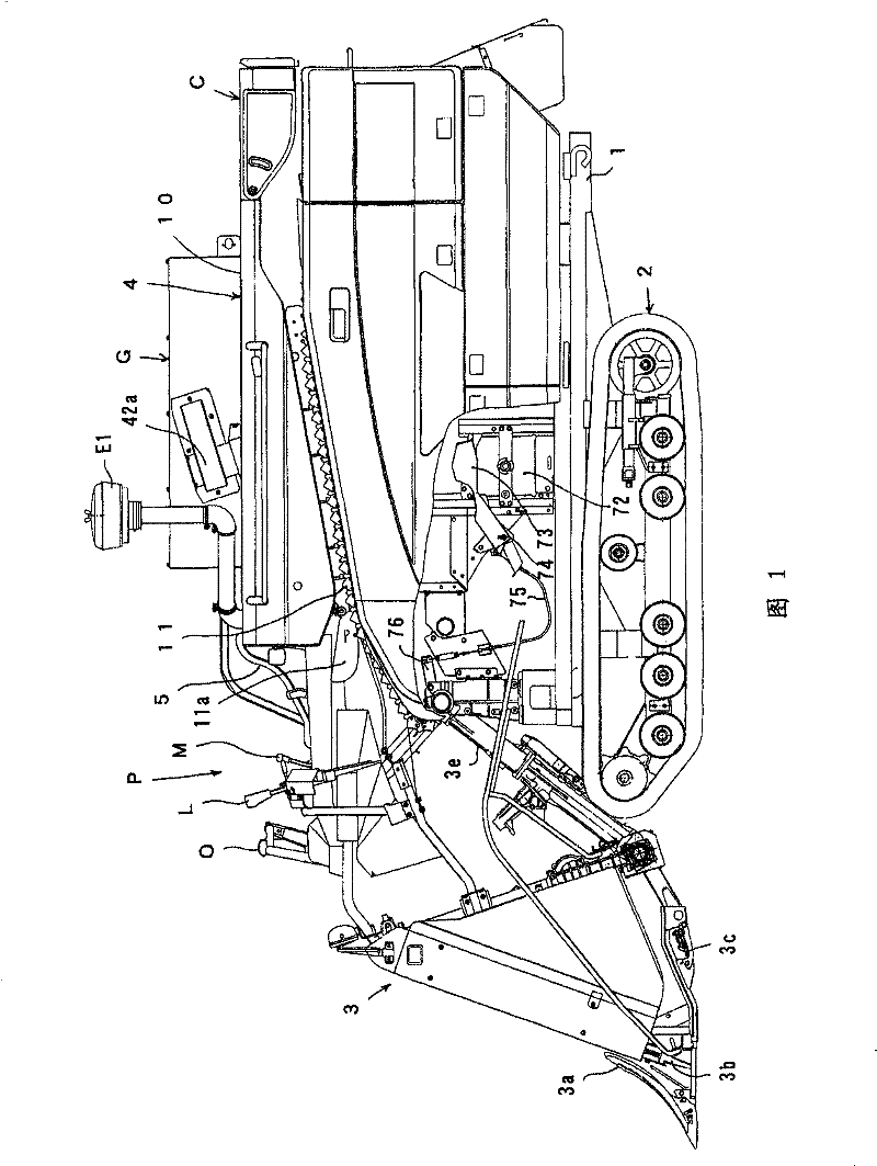
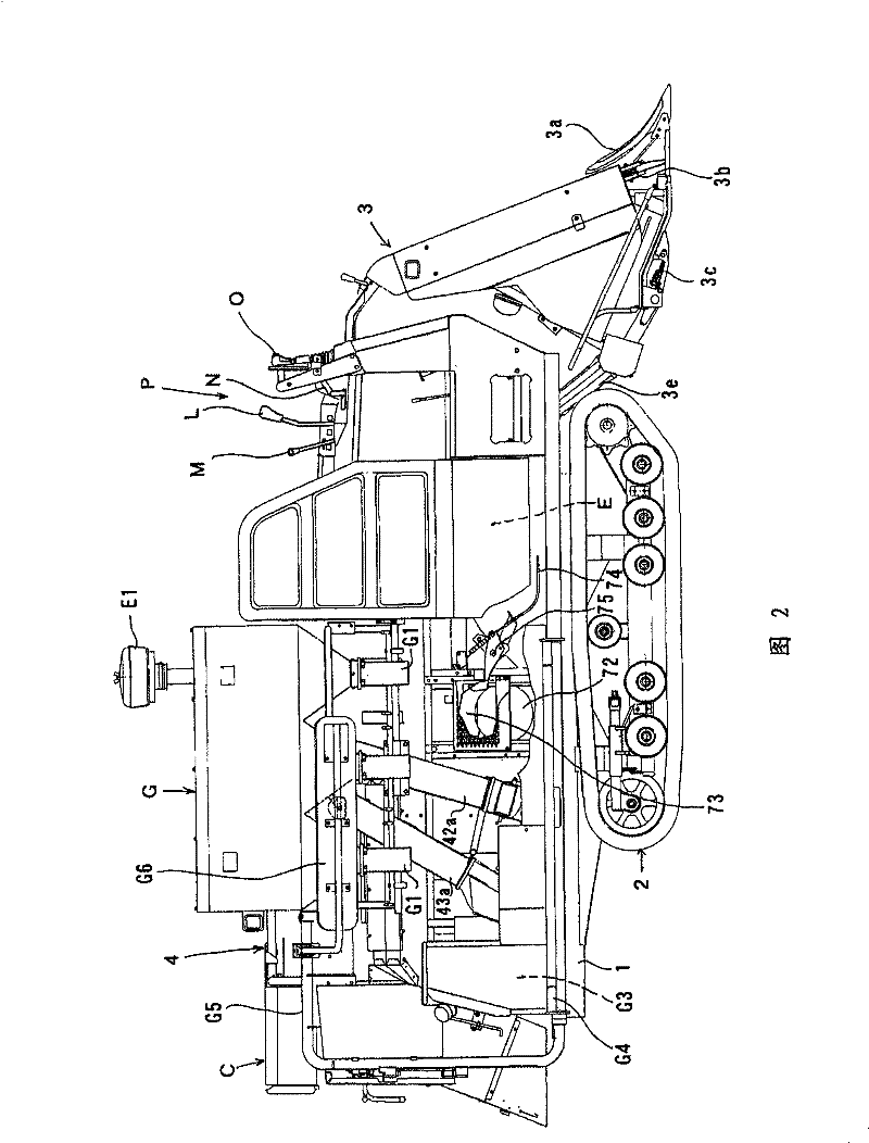
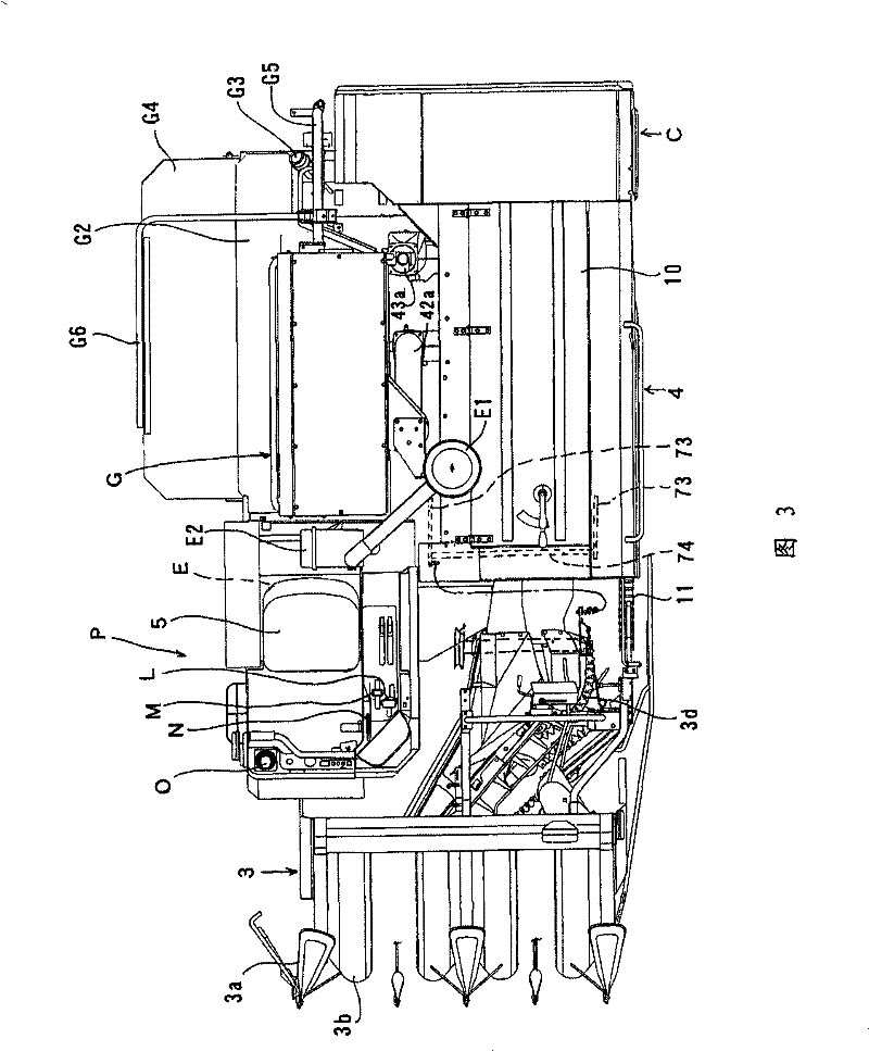
[0030] First, the structure of the body of a combine will be described based on FIG.1, FIG.2, FIG.3.

[0031] On the front side of the car body 1 equipped with a traveling device 2 with crawlers, a harvesting device 3 that can be raised and lowered is installed, a threshing device 4 is mounted on the upper side of the car body 1, and a hopper-type grain storage is installed on the right side of the threshing device 4 As for the device G, a discharge straw cutter C is provided on the rear side of the threshing device 4 .

[0032] The above-mentioned harvesting device 3 includes: a separating body 3a for separating rice straws, a pulling device 3b for pulling up the separated rice straws, a scraping device (not shown) for scraping the pulled rice straws, and a harvester for harvesting the scraped rice straws. The cutting blade device 3c of the stalk,...


PUM


Abstract

The present invention relates to a combine harvester. The invention settles a problem of harvest loss caused by the discharging of grains on a swinging sorting shelf to the outside of a threshing device, and the precision and efficiency of the threshing operation are increased. On a first dust discharging opening (21) which is equipped to the back left side part of a dust discharging processing chamber (18), a first discharging guiding plate (29) which is provided with a first inclined surface (29a) that guides the dust material discharged from a first dust opening (21) to the right back flowfor falling to the surface of farmland. On a second dust discharging opening (23) which is equipped to the back right side part of the dust discharging processing chamber (18), a second discharging guiding plate (24) which is provided with a second inclined surface (24a) that guides the dust material discharged from the second dust discharging opening (23) to the right back flow for falling to the surface of the farmland and a third inclined surface (24b) that guides the dust material discharged from the second dust discharging opening (23) to the right back flow of the threshing device (4) for falling to the surface of the farmland is provided.

Description

technical field [0001] The present invention relates to combine harvesters. Background technique [0002] Conventionally, the following combine harvesters are known: a harvesting device is provided on the front side of a vehicle body equipped with a traveling device, a threshing device is provided on the upper side of the vehicle body, and a grain storage device is provided on the right side of the threshing device. The upper part of the threshing device is provided with a threshing chamber equipped with a threshing drum, a feed chain is provided on the left side of the threshing chamber, and a dust discharge treatment chamber is provided on the right side of the threshing chamber. The dust discharge processing drum rotating counterclockwise connects the rear end of the threshing chamber and the front end of the dust discharge processing chamber with a communication port, and a shaking sorting shelf is set under the threshing drum and the dust discharge processing chamber. ...

Claims


Application Information

Patent Timeline
Patent Type & Authority Patents(China)
IPC IPC(8): A01D41/02A01F12/18A01F12/54
Inventor 竹内贤一朗大崎正美
Owner ISEKI & CO LTD
Learn More