
Pneumatic optical degeneration image sequence self-adapting correction method

A degraded image and aero-optics technology, applied in the field of interdisciplinary science, can solve problems such as limited performance, difficult to achieve, random changes, etc., and achieve the effect of improving correction efficiency, narrowing the scope of optimization, and effective correction

Inactive Publication Date: 2011-08-10
HUAZHONG UNIV OF SCI & TECH
View PDF0 Cites 0 Cited by
  • Summary
  • Abstract
  • Description
  • Claims
  • Application Information

AI Technical Summary

Problems solved by technology

Due to the complex and variable influence of the turbulent flow field on the target imaging, it is difficult to measure the turbulent optical point spread function, and its form cannot be determined in advance, and it changes randomly.
Therefore, the above method is difficult to meet the practical application
[0005] The two-frame degraded image correction algorithm proposed by Zhang Tianxu and Hong Hanyu (see Zhang Tianxu, Hong Hanyu, Shen Jun. Restoration algorithms for turbulence-degraded images based on optimized estimation of discrete values ​​of overall point spread functions. Optical Engineering, 2005, 44 (1 )), although it can achieve better correction for aero-optical degradation images, but it is necessary to specify the size of the support domain of the point spread function, which is difficult to do in practical applications, which limits the effectiveness of the method
In addition, the information of sequence images is not fully utilized, and there is no computable criterion for quality evaluation of corrected images

Method used


Image

  • Pneumatic optical degeneration image sequence self-adapting correction method
  • Pneumatic optical degeneration image sequence self-adapting correction method
  • Pneumatic optical degeneration image sequence self-adapting correction method

Examples


Embodiment Construction

[0076] Below in conjunction with accompanying drawing and example the present invention is described in further detail.

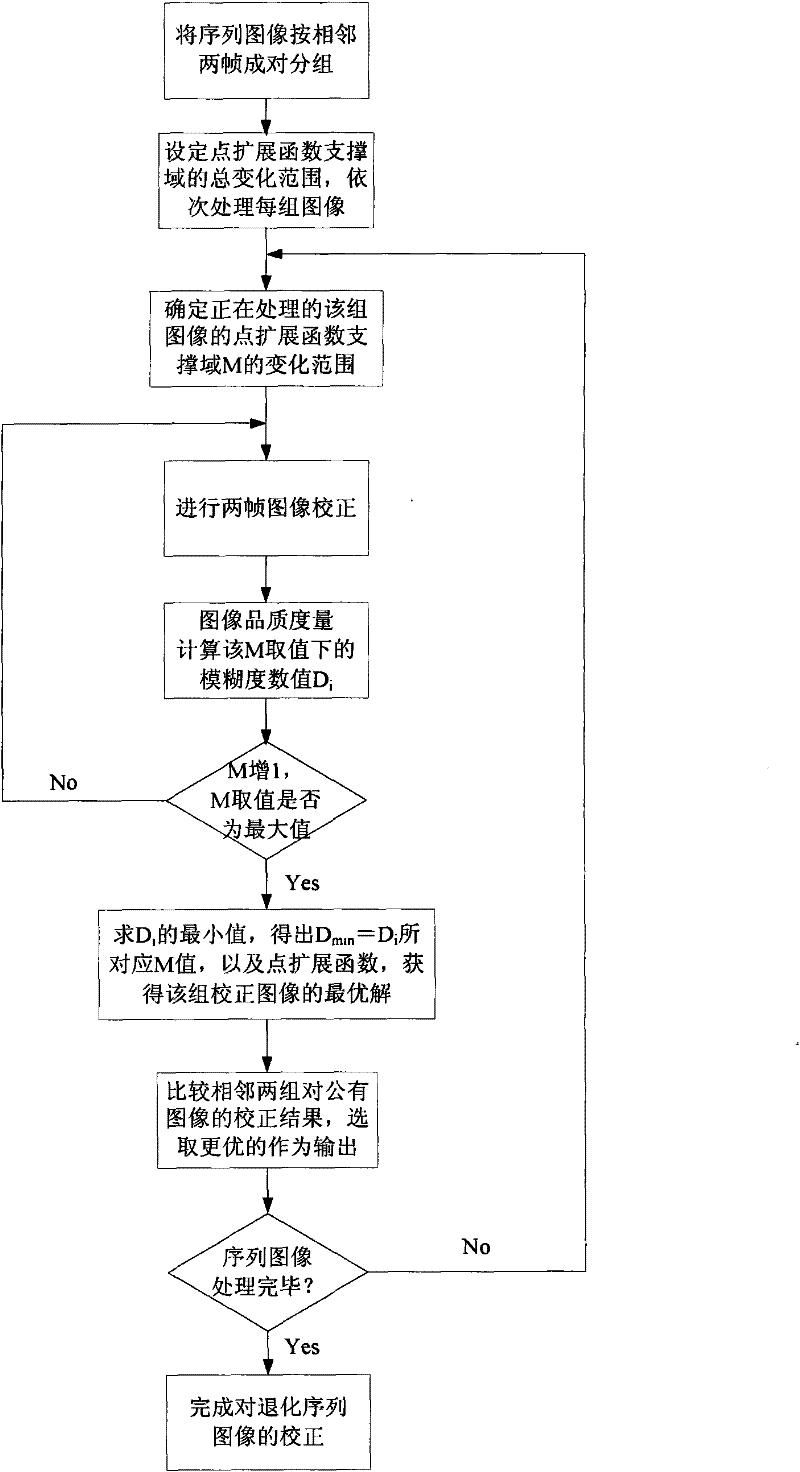
[0077] (1) The degraded image sequence (f 1 , f 2 , f 3 ,..., f T-2 , f T-1 , f T ) are grouped in pairs by two adjacent frames, and each group of images constitutes the basic processing object of correction and restoration operations:

[0078] (f 1 , f 2 ), (f 2 , f 3 )(f 3 , f 4 ),..., (f T-2 , f T-1 ), (f T-1 , f T )

[0079] T is the number of frames of the degraded image;

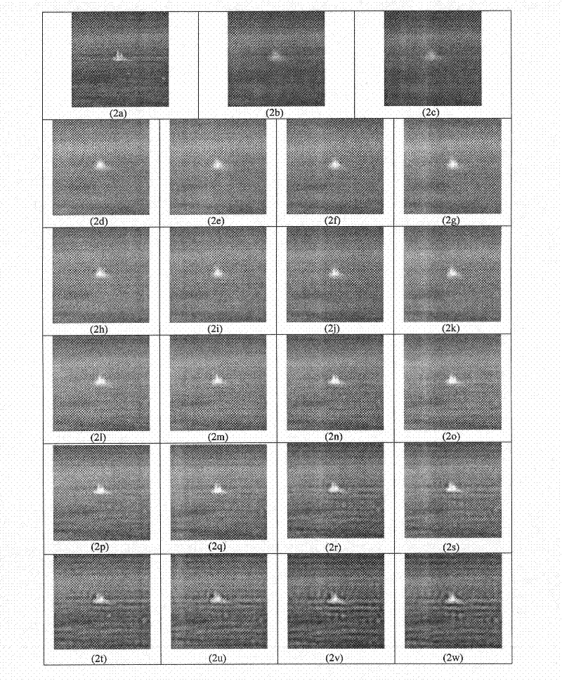
[0080] Such as simulation image image sequence ( figure 2 a, 2b and Figure 5 a, 5b)), the first frame, the second frame image, the second frame, and the third frame image are grouped in pairs, and the subsequent simulation images are similarly processed, and the actual wind tunnel image ( Figure 7 a, 7b) and Figure 8 a, 8b)) Divide the sequence images into a group of frames 0 and 1, frames 1 and 2, and so on for sequence image correction.

[0081] (2) Set th...


PUM


Abstract

The invention discloses a pneumatic optical degeneration image sequence self-adapting correction method, comprising the following steps: (1) grouping the degeneration sequence image in pair according to the adjacent frames; (2) specifying the total change range of the point spread function support domain; (3) determining the support domain change range of the point spread function of the current set of images; (4) performing the image correction of the current set of images; (5) measuring the image recovery effect quality; (6) performing the iterative recursive estimation of the optimum pointspread function support domain and its point spread function based on the measurement result of the correction image quality; (7) selecting the best correction result of the common frame of the adjacent two sets of images; (8) performing the cyclic execution to complete the correction of the degeneration sequence image. When the point spread function support domain is unknown, the best image correction result is obtained using the image quality measurement criterion and the optimization range is reduced using the information of the adjacent frames in the sequence image and the correction efficiency is increased and the pneumatic optical degeneration image sequence is effectively and quickly corrected.

Description

technical field [0001] The invention belongs to the field of interdisciplinary science and technology combining aero-optics and image processing, and in particular relates to an adaptive correction method for aero-optics degraded image sequences. Background technique [0002] Aero-optics is a subject that studies the influence of high-speed flow on imaging and detection of high-speed aircraft. When a high-speed aircraft with an optical imaging detection system flies in the atmosphere, a complex flow field is formed between the optical hood and the incoming flow, which causes optical wavefront transmission distortion or transmission interference in addition to thermal radiation to the optical imaging detection system, causing The offset, shake, and blur of the image of the observed object are called aero-optical transmission effects. This effect reduces the effectiveness of the imaging detection system and in severe cases completely disables it. Therefore, it is necessary t...

Claims


Application Information

Patent Timeline
Patent Type & Authority Patents(China)
IPC IPC(8): G06T5/50
Inventor 张天序余铮王进关静武道龙洪汉玉陈荣华
Owner HUAZHONG UNIV OF SCI & TECH
Learn More